


Optional Hardware and Software M400E Ozone Analyzer Operator’s Manual
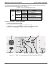
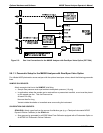
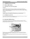
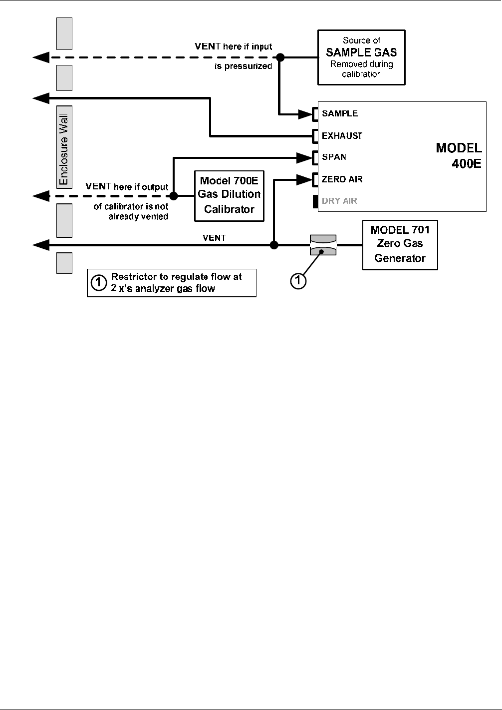
Figure 5-5: Gas Line Connections for the M400E Analyzer with Zero/Span Valve Option (OPT-50A)
5.6.1.1. Pneumatic Setup for the M400E Analyzer with Zero/Span Valve Option
For a Model 400E photometric ozone analyzer with the optional zero/span valves, attach the following pneumatic
lines:
SAMPLE GAS SOURCE:
Attach a sample inlet line to the SAMPLE inlet fitting.
Sample Gas pressure must equal ambient atmospheric pressure (1.0 psig)
In applications where the sample gas is received from a pressurized manifold, a vent must be placed
on the sample gas line. This vent line must be:
At least 0.2m long
No more than 2m long
Vented outside the shelter or immediate area surrounding the instrument
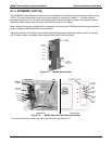
CALIBRATION GAS SOURCES:
SPAN GAS: Attach a gas line from the source of calibration gas (e.g. a Teledyne Instruments M700E
Dynamic Dilution Calibrator) to the SPAN inlet.
Span gas can by generated by a M700E Mass Flow Calibrator equipped with a Photometer Option or
an M703E UV Photometric Ozone Calibrator.
50 04315 Rev. C1