


M400E Ozone Analyzer Operator’s Manual General Troubleshooting & Repair of the M400E Analyzer
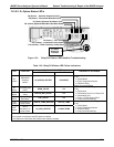
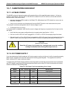
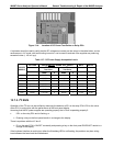
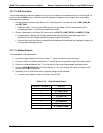
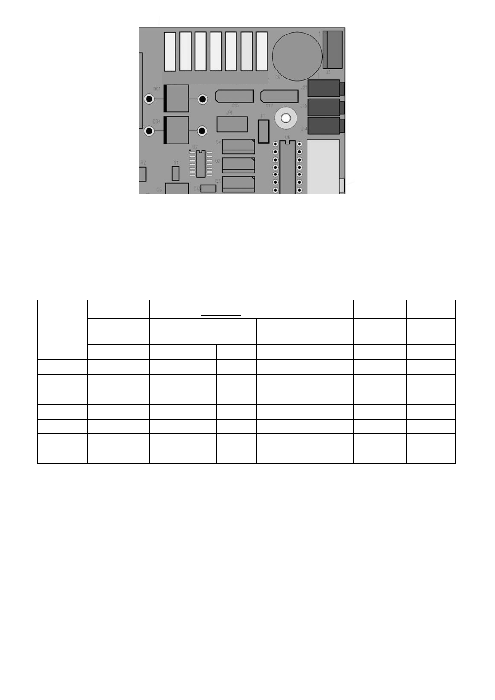
TP1 TP2 TP3 TP4 TP5 TP6 TP7
DGND +5V AGND +15V -15V +12R 12V
Figure 13-4: Location of DC Power Test Points on Relay PCA
A voltmeter should be used to verify that the DC voltages are correct per the values in the table below, and an
oscilloscope, in AC mode, with band limiting turned on, can be used to evaluate if the supplies are producing
excessive noise (> 100 mV p-p).
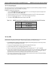
Table 13-7: DC Power Supply Acceptable Levels
VOLTAGE
CHECK
RELAY BOARD TEST POINTS
MIN V MAX V
FROM
Test Point
TO
Test Point
POWER
SUPPLY
NAME # NAME #
PS1 +5 DGND 1 +5 2 +4.80 +5.25
PS1 +15 AGND 3 +15 4 +13.5 +16.0
PS1 -15 AGND 3 -15V 5 -14.0 -16.0
PS1 AGND AGND 3 DGND 1 -0.05 +0.05
PS1 Chassis DGND 1 Chassis N/A -0.05 +0.05
PS2 +12 +12V Ret 6 +12V 7 +11.8 +12.5
PS2 DGND +12V Ret 6 DGND 1 -0.05 +0.05
13.7.3. I
2
C BUS
Operation of the I
2
C bus can be verified by observing the behavior of D1 on the relay PCA & D2 on the valve
driver PCA in conjunction with the performance of the front panel display.
Assuming that the DC power supplies are operating properly the I
2
C bus is operating properly if:
If D1 on the relay PCA and is flashing, or
Pressing a key on the front panel results in a change to the display.
There is a problem with the I
2
C bus if
D1 on the relay PCA is ON/OFF constantly and pressing a key on the front panel DOES NOT results in a
change to the display.
If the keyboard interface is working but either the Watchdog LED is not flashing, the problem may be a wiring
issue between the board and the motherboard
04315 Rev. C1 247