General Troubleshooting & Repair of the M400E Analyzer M400E Ozone Analyzer Operator’s Manual
13.10. REPAIR PROCEDURES
13.10.1. REPAIRING SAMPLE FLOW CONTROL ASSEMBLY
The Critical Flow Orifice is part of the Flow Control Assembly located on the sample pump assembly or
optionally in the ozone generator for instruments with the IZS option. The jewel orifice is protected by a sintered
filter, so it is unusual for the orifice to need replacing, but it is possible for the sintered filter and o-rings to need
replacing. See the Spare Parts list in Appendix B for part numbers and kits.
Procedure:
1. Turn off Power to the analyzer.
2. Locate the flow control assembly attached to the sample pump. See Figure 3-4.
3.
Disconnect the pneumatic fittings.
4. Remove the assembly from the sample pump by disconnecting the ¼” tube fitting on the pump inlet
elbow.
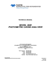
5. The inlet end of the assembly is the straight ¼” tube to 1/8” male NPT fitting. Remove the fitting and the
components as shown in the exploded view in the following figure.
6. Replace the O-rings and the sintered filter.
7. If you are replacing the Critical Flow Orifice itself, make sure that the side with the red colored sapphire
jewel is facing downstream to the flow gas flow.
8. Re-assemble in reverse order. See the Spares List in Appendix B for part numbers.
9. After re-connecting the power and pneumatic lines, verify flow rate is between 720 and 880 cc/min.
Pneumatic Connector, Male 1/4”
P/N FT0000070
Spring
P/N HW0000020
Sintered Filter
P/N FL0000001
Critical Flow Orifice
P/N 00094-1000
O-Ring
P/N OR0000001
Housing
P/N 00085-0000
Figure 13-5: Critical Flow Orifice Assembly (Instruments without IZS)
256 04315 Rev. C1