Advanced FEATURES of the M400E analyzer M400E Ozone Analyzer Operator’s Manual
To adjust the zero and span signal levels of the current outputs, select the ANALOG I/O CONFIGURATION
submenu (see Figure 7-4) then press:
From the
AIO CONFIGURATION SUBMENU
(See figure 7-4)
DIAG ANALOG I/O CONFIGURATION
PREV NEXT ENTR EXIT
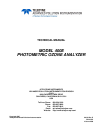
Continue pressing SET> until you reach the
output to be configured
DIAG AIO CONC_OUT_2: 5V, CONC2, NOCAL
<SET SET> EDIT EXIT
Continue pressing SET> until ...
DIAG AIO CONC_OUT_2: CALIBRATED:NO
<SET SET> CAL EXIT
DIAG AIO CONC_OUT_2: RANGE: CURR
SET> EDIT EXIT
DIAG AIO CONC_OUT_2: CURR-Z: 0 mV
U100 UP10 UP DOWN DN10 D100 ENTREXIT
DIAG AIO CONC_OUT_2: CURR-S: 5000 mV
U100 UP10 UP DOWN DN10 D100 ENTREXIT
DIAG AIO CONC_OUT_2: CALIBRATED: YES
<SET SET> CAL EXIT
These menu’s
only appear if
AUTO-CAL is
turned OFF
These keys increase / decrease
the analog output signal level
(not the value on the display)
by 100, 10 or 1 counts.
Continue adjustments until the
voltage measured at the output
of the analyzer and/or the input
of the recording device matches
the value in the upper right hand
corner of the display (within the
tolerances
listed in Table 7-7
DIAG AIO AOUTS CALIBRATED: NO
SET> CAL EXIT
DISPLAYED AS = CHANNEL
CONC_OUT_1 = A1
CONC_OUT_2 = A2
TEST OUTPUT = A4
106 04315 Rev. C1