


M400E Ozone Analyzer Operator’s Manual Theory of Operation
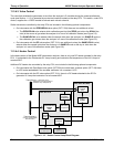
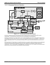
11.3.7.1. Photometer Electronic Operation
Sensor Inputs
Absorption tube
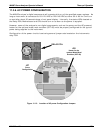
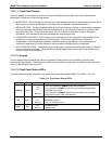
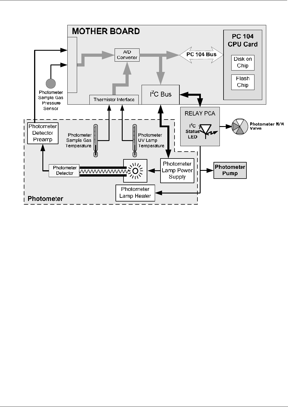
Figure 11-17: O
3
Photometer Electronic Block Diagram
Like the O
3
photometer and its subcomponents act as peripheral devices operated by the CPU via the
motherboard. Communications to and from the CPU are handled by the motherboard.
Outgoing commands for the various devices such as the photometer pump, the UV lamp power supply the U\V
Lamp heater are issued via the I
2
C bus to circuitry on the relay PCA which turns them ON/OFF. The CPU also
issues commands over the I
2
C bus that cause the relay PCA to cycle the measure/reference valve back and
forth.
Incoming date the UV light detector is amplified locally then converted to digital information by the motherboard.
Output from the photometers temperature sensors is also amplified and converted to digital data by the
motherboard. The O
3
concentration of the sample gas is computed by the CPU using this data (along with gas
pressure and flow data received from the M400E’s pressure sensors.
04315 Rev. C1 211