


Theory of Operation M400E Ozone Analyzer Operator’s Manual
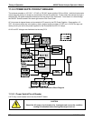
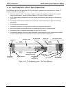
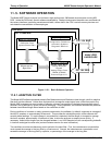
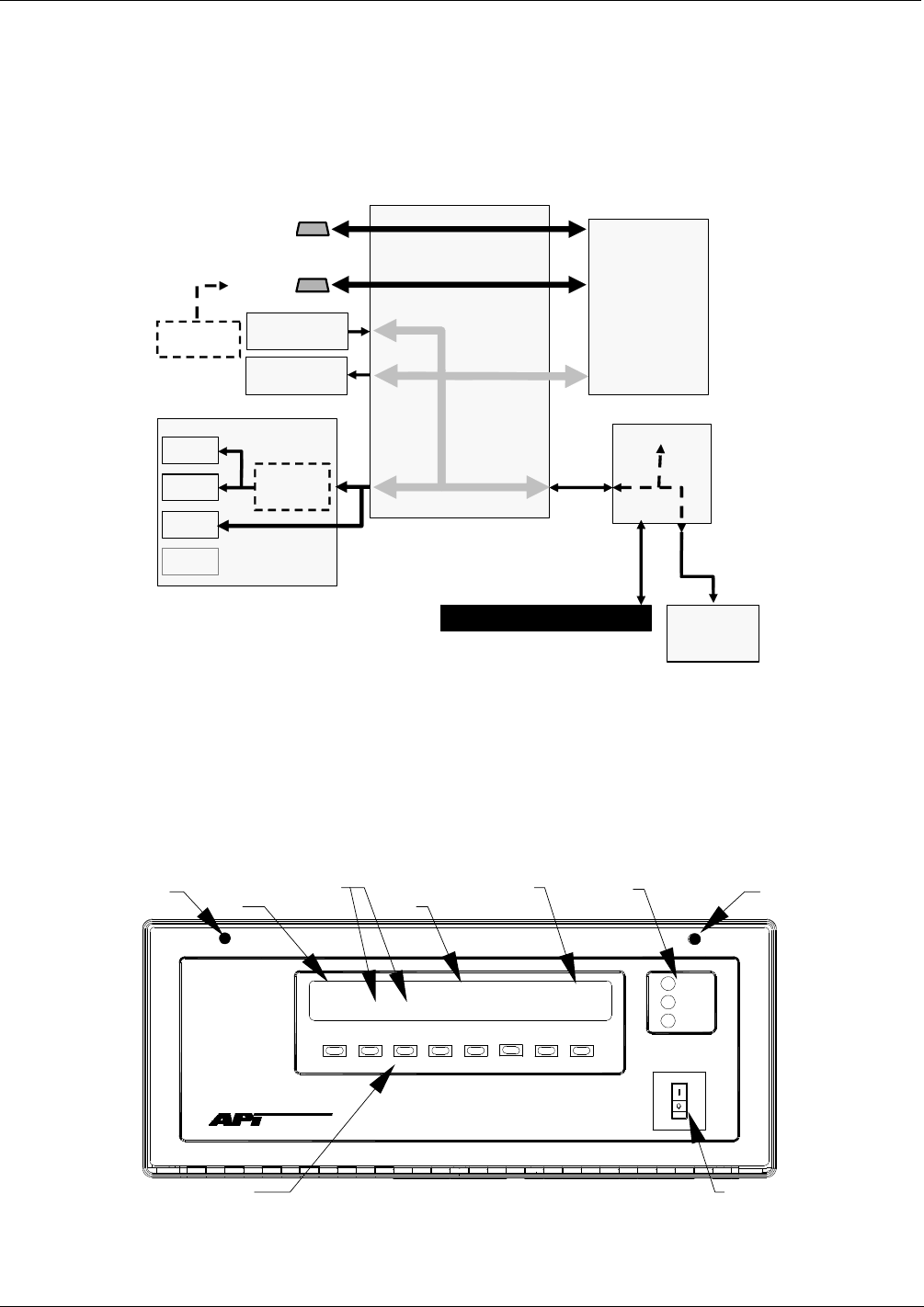
11.4. INTERFACE
The analyzer has several ways to communicate the outside world. Users can input data and receive information
directly via the front panel keypad and display. Direct communication with the CPU is also available by way of
the analyzers RS232 & RS485 I/O ports. The analyzer can also send and receive different kinds of information
via its external digital i/o connectors and the three analog outputs located on the rear panel.
Mother
Board
Status Outputs:
1 – 8
Control Inputs:
1 – 6
CPU
RS–232 ONLY
RS-232 or RS–485
KEYBOARD
RELAY
BOARD
PC/104 BUS
FRONT PANEL DISPLAY
I
2
C BUS
I
2
C BUS
Analog Outputs
A1
A2
A3
Optional
4-20 mA
COMM B
Female
A4ST
COMM
A
Male
ETHERNET
OPTION
Figure 11-19: Interface Block Diagram
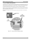
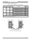
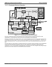
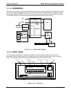
11.4.1. FRONT PANEL
The Front panel of the analyzer is hinged at the bottom and may be opened to gain access to various
components mounted on the panel itself or located near the front of the instrument (such as the Particulate
Filter). Two fasteners located in the upper right and left corners of the panel lock it shut.
POWER
FAULT
CAL
SAMPLE
GAS FILTER CORRELATION ANALYZER - MODEL 300E
SAMPLE A RANGE = 50 PPM
CO = 40.0
<TST
TST> CAL
SETUP
MODE FIELD
KEY DEFINITIONS
MESSAGE FIELD
CONCENTRATION FIELD STATUS LED’s
KEYBOARD
ON / OFF SWITCH
FASTENE
R
FASTENER
Figure 11-20: Front Panel
214 04315 Rev. C1