


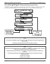

M400E Ozone Analyzer Operator’s Manual Basic Operation of the M400E Analyzer
The user can set the units of measure, measure span and signal scale of each output in a variety of
combinations.
EXAMPLE:
A1 OUTPUT: Output Signal = 0-5 VDC representing 0-1000 ppb concentration values
A2 OUTPUT: Output Signal = 0 – 10 VDC representing 0-500 ugm concentration values.
Both the
A1 and A2 outputs can be:
Configured full scale outputs of: 0 - 0.1 VDC; 0 - 1VDC; 0 - 5VDC or; 0 - 10VDC.
Equipped with optional 0-20 mADC current loop drivers (OPT 41, see Section 5.4) and configured for any
curre
nt output within that range (e.g. 0-20, 2-20, 4-20, etc.).
The user may also add a signal offset independently to each output (see Section 7.4.5) to match the electronic
input req
uirements of the recorder or data logger to which the output is connected.
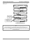
DEFAULT SETTINGS
The default setting for these the reporting ranges of the analog output channels A1 and A2 are:
SNGL mode
0 to 400.0 ppb
0 to 5 VDC
Reporting range span may be viewed via the front panel by viewing the
RANGE test function. If the DUAL or
AUTO modes are selected, the RANGE test function will be replaced by two separate functions, RANGE1 &
RANGE2. Reporting range status is also available as output via the external digital I/O status bits (see
Section 3.3.3).
NOTE
Upper span limit setting for the individual range modes are shared. Resetting the span limit in one mode
also resets the span limit for the corresponding range in the other modes as follows:
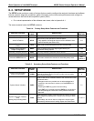
SNGL DUAL AUTO
Range Range1 (Low) Low Range
Range2 (Hi) High Range
04315 Rev. C1 71