


Model 400E Instruction Manual APPENDIX A-4: M400E Signal I/O Definitions, Revision D.4
APPENDIX A-4: M400E Signal I/O Definitions, Revision D.4
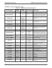
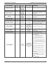
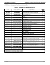
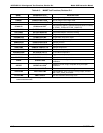
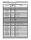
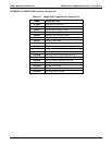
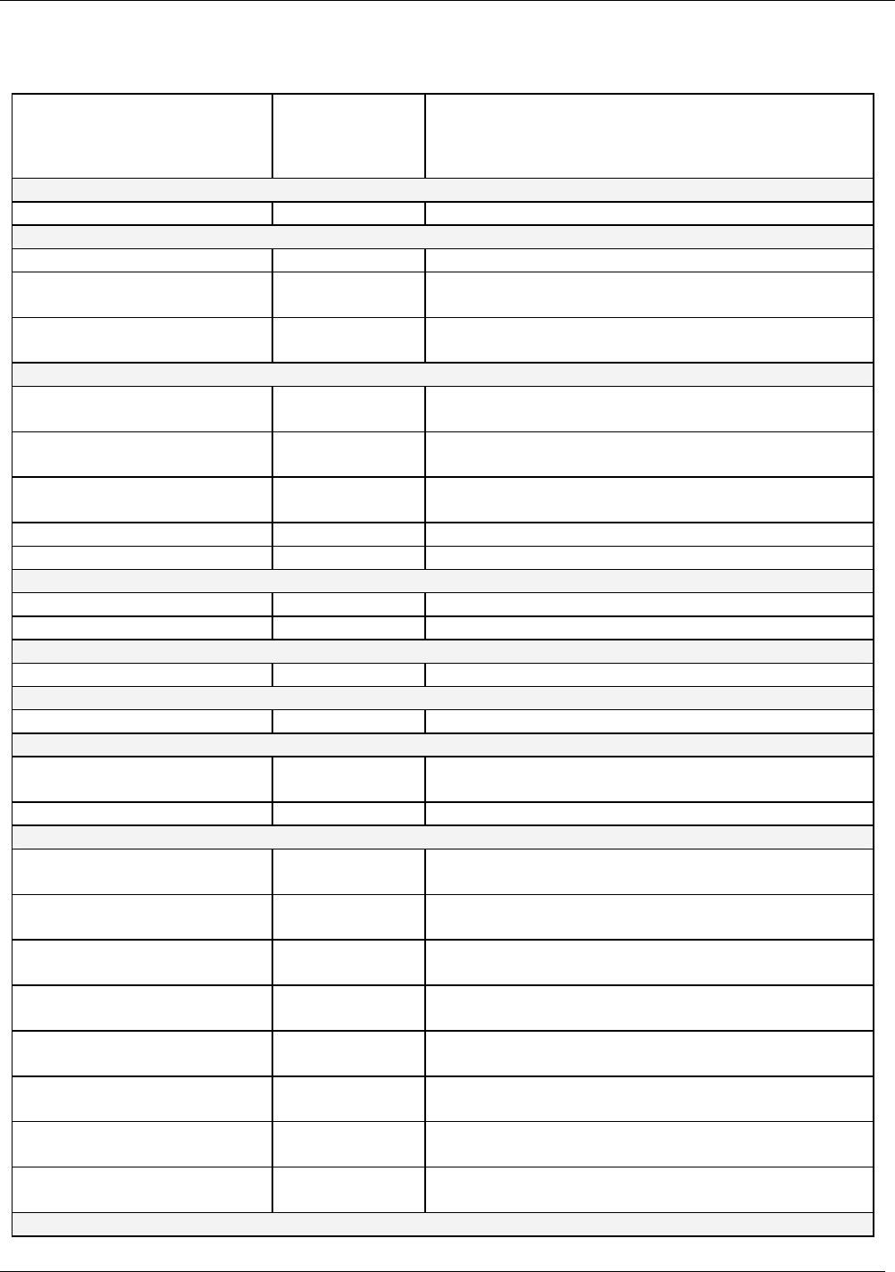
Table A-4: M400E Signal I/O Definitions, Revision D.4
SIGNAL NAME
BIT OR
CHANNEL
NUMBER
DESCRIPTION
Internal inputs, U7, J108, pins 9–16 = bits 0–7, default I/O address 322 hex
0–7 Spare
Internal outputs, U8, J108, pins 1–8 = bits 0–7, default I/O address 322 hex
0–5 Spare
I2C_RESET
6
1 = reset I2C peripherals
0 = normal
I2C_DRV_RST
7
0 = hardware reset 8584 chip
1 = normal
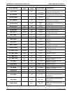
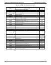
Control inputs, U11, J1004, pins 1–6 = bits 0–5, default I/O address 321 hex
EXT_ZERO_CAL
0
0 = go into zero calibration
1 = exit zero calibration
EXT_LOW_SPAN_CAL
1
1
0 = go into low span calibration
1 = exit span calibration
EXT_SPAN_CAL
1
2
0 = go into span calibration
1 = exit span calibration
3–5 Spare
6–7 Always 1
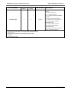
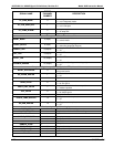
Control inputs, U14, J1006, pins 1–6 = bits 0–5, default I/O address 325 hex
0–5 Spare
6–7 Always 1
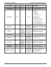
Control outputs, U17, J1008, pins 1–8 = bits 0–7, default I/O address 321 hex
0–7 Spare
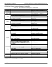
Control outputs, U21, J1008, pins 9–12 = bits 0–3, default I/O address 325 hex
0–3 Spare
Alarm outputs, U21, J1009, pins 1–12 = bits 4–7, default I/O address 325 hex
ST_SYSTEM_OK2
4
1 = system OK
0 = any alarm condition or in diagnostics mode
5–7 Spare
A status outputs, U24, J1017, pins 1–8 = bits 0–7, default I/O address 323 hex
ST_SYSTEM_OK
0
0 = system OK
1 = any alarm condition
ST_CONC_VALID
1
0 = conc. valid
1 = hold off or other conditions
ST_HIGH_RANGE
2
0 = high auto-range in use
1 = low auto-range
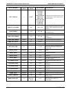
ST_ZERO_CAL
3
0 = in zero calibration
1 = not in zero
ST_SPAN_CAL
4
0 = in span calibration
1 = not in span
ST_TEMP_ALARM
5
0 = any temperature alarm
1 = all temperatures OK
ST_FLOW_ALARM
6
0 = any flow alarm
1 = all flows OK
ST_PRESS_ALARM
7
0 = any pressure alarm
1 = all pressures OK
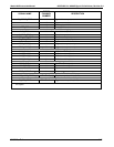
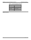
B status outputs, U27, J1018, pins 1–8 = bits 0–7, default I/O address 324 hex
04402 Rev D.4 A-19