Basic Operation of the M400E Analyzer M400E Ozone Analyzer Operator’s Manual
6.4.4. SETUP RNGE: ANALOG OUTPUT REPORTING RANGE
CONFIGURATION
6.4.4.1. Physical Range versus Analog Output Reporting Ranges
Functionally, the Model 400E photometric analyzer has one hardware “physical range” that is capable of
determining O
3
concentrations between 0 ppb and 10,000 ppb. This architecture improves reliability and
accuracy by avoiding the need for extra, switchable, gain-amplification circuitry. Once properly calibrated, the
analyzer’s front panel will accurately report concentrations along the entire span of its physical range.
Because, most applications use only a small part of the analyzer’s physical range, the width of the M400E
analyzer’s physical range can create data resolution problems for most analog recording devices. For example,
in an application where the expected concentration of O
3
is typically less than 500 ppb, the full scale of expected
values is only 5% of the instrument’s 10,000 ppm physical range. Unmodified, the corresponding output signal
would also be recorded across only 5% of the range of the recording device.
The M400E solves this problem by allowing the user to select a scaled reporting range for the analog outputs
that only includes that portion of the physical range relevant to the specific application.
NOTE
Only the reporting range of the analog outputs is scaled.
Both the iDAS values stored in the CPU’s memory and the concentration values reported on the front
panel are unaffected by the settings chosen for the reporting range(s) of the instrument.
6.4.4.2. Analog Output Ranges for O
3
Concentration
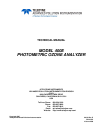
The analyzer has two active analog output signals related to O
3
concentration that are accessible through a
connector on the rear panel (see Figure 3-2).
Not Used on M400E
NALOG OUT
A1 A2
3
4
+ - + - + - + -
O
3
concentration
outputs
HIGH range when DUAL
mode is selected
Test Channel
See Section
7.4.6
LOW range when DUAL
mode is selected
Figure 6-3: Analog Output Connector Pin Out
The A1 and A2 channels output a signal that is proportional to the O
3
concentration of the sample gas. They
can be configured:
With independent reporting ranges reporting a “single” output signal (
SNGL Mode, see Section 6.4.4.3) o
Be to operate completely independently (
DUAL mode, see Section 6.4.4.4).
Or to automatically switch between the two ranges dynamically as the concentration value fluctuates
(
AUTO modes, see Section 6.4.4.5).
70 04315 Rev. C1