


M400E Ozone Analyzer Operator’s Manual Getting Started
3.3.2. ANALOG OUTPUT CONNECTIONS
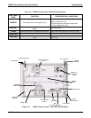
The M400E is equipped with several analog output channels accessible through a connector on the back panel
of the instrument (see Figure 3-2).
Cha
nnels A1 and A2 output a signal that is proportional to the O
3
concentration of the sample gas.
The default analog output voltage setting of these channels is 0 to 5 VDC with a reporting range of 0 to
500 ppb.
An optional Current Loop output is available for each.
The output labeled A4 is special. It can be set by the user to output any one a variety of diagnostic test
functions.
The default analog output voltage setting of these channels is also 0 to 5 VDC.
See Section 7.4.6 for a list of available functions a
nd their associated reporting range.
There is no optional Current Loop output available for Channel A4.
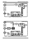
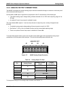
To access these signals attach a strip chart recorder and/or data-logger to the appropriate analog output
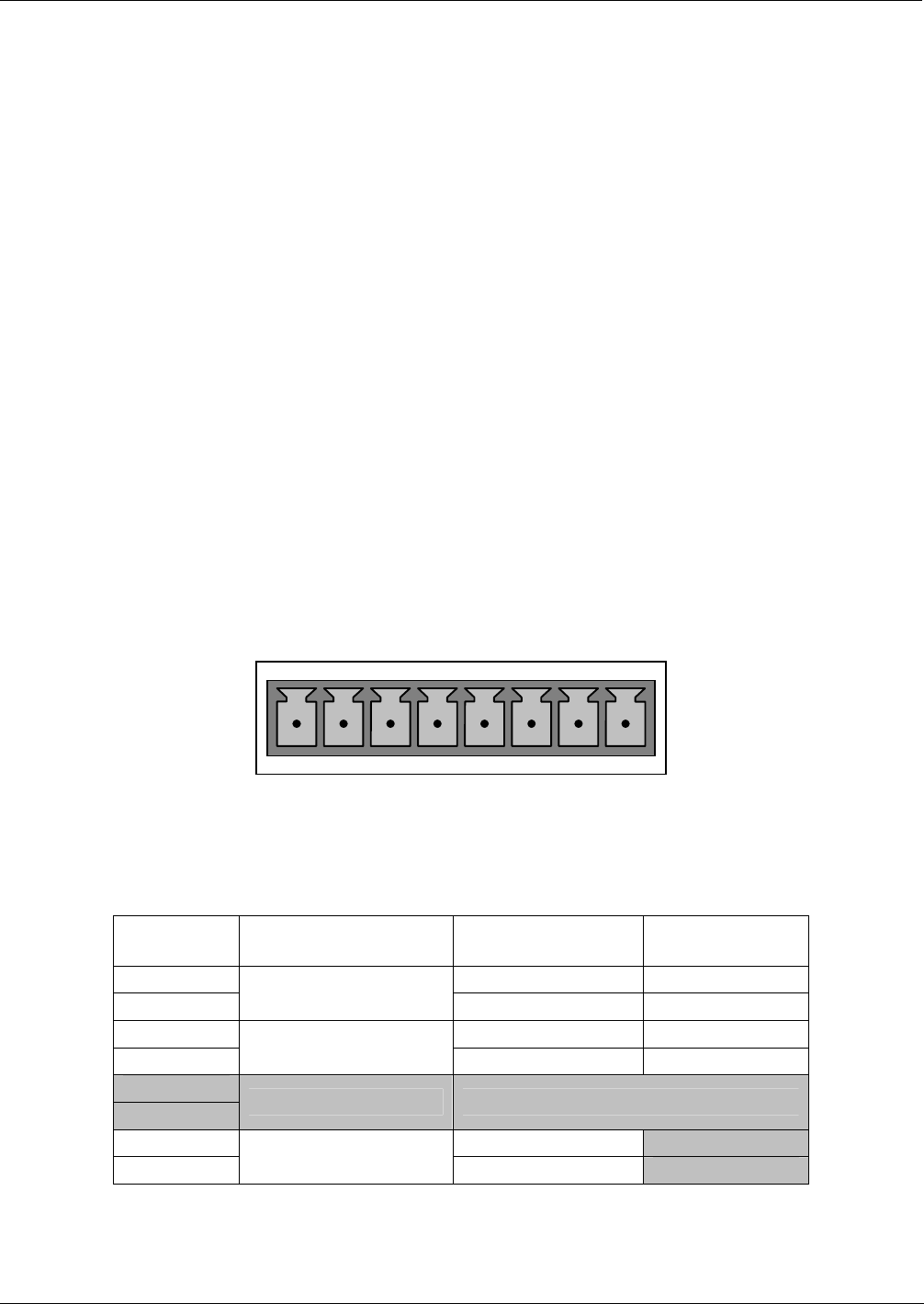
connections on the rear panel of the analyzer. Pin-outs for the analog output connector are:
ANALOG OUT
A1 A2 A3 A4
+ - + - + - + -
Figure 3-7: M400E Analog Output Connector
Table 3-4: Analog Output Pin Outs
Pin Analog Output
Standard Voltage
Output
Current
Loop Option
1 V Out I Out +
2
A1
Ground I Out -
3 V Out I Out +
4
A2
Ground I Out -
5
6
A3 NOT USED
7 V Out Not Available
8
A4
Ground Not Available
To change the settings for the analog output channels, see Section 7.4
04315 Rev. C1 17