


M400E Ozone Analyzer Operator’s Manual Advanced FEATURES of the M400E analyzer
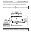
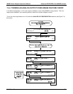
7.4.2.4. Manual Adjustment of Current Loop Output Span and Offset
A current loop option may be purchased for the A1 and A2 Analog outputs of the analyzer. This option places
circuitry in series with the output of the D-to A converter on the motherboard that changes the normal DC voltage
output to a 0-20 milliamp signal. The outputs can be ordered scaled to any set of limits within that 0-20 mA
range, however most current loop applications call for either 0-20 mA or 4-20mA range spans. All current loop
outputs have a + 5% over range. Ranges whose lower limit is set above 1 mA also have a –5 under range.
To switch an analog output from voltage to current loop, follow the instructions in Section 7.4.3 and select
CURR
from the list of options on the “Output Range” menu.
Adjusting the signal zero and span levels of the current loop output is done by raising or lowering the voltage
output of the D-to-A converter circuitry on the analyzer’s motherboard. This raises or lowers the signal level
produced by the Current Loop Option circuitry.
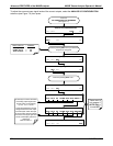
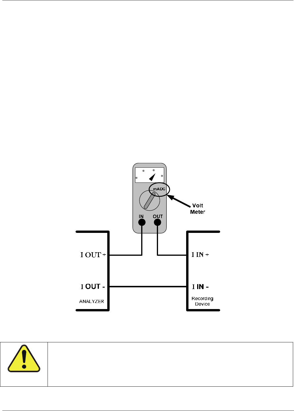
The software allows this adjustment to be made in 100, 10 or 1 count increments. Since the exact amount by
which the current signal is changed per D-to-A count varies from output-to-output and instrument–to–instrument,
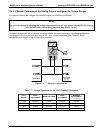
you will need to measure the change in the signal levels with a separate, current meter placed in series with the
output circuit. See Figure 3-7 for pin assignments and diagram of the anal
og output connector.
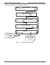
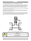
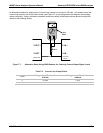
Figure 7-6: Setup for Checking Current Output Signal Levels
CAUTION
General Safety Hazard
DO NOT EXCEED 60 V PEAK VOLTAGE BETWEEN CURRENT LOOP OUTPUTS AND
INSTRUMENT GROUND.
04315 Rev. C1 105