


M400E Ozone Analyzer Operator’s Manual General Troubleshooting & Repair of the M400E Analyzer
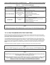
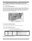
13.2. USING THE ANALOG OUTPUT TEST CHANNEL
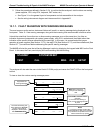
The signals available for output over the M400E’s analog output channel can also be used as diagnostic tools.
See Section 7.4 for instruction on activating the analog output and selecting a
function.
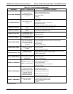
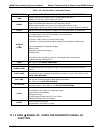
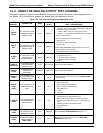
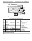
Table 13-3: Test Channel Outputs as Diagnostic Tools
TEST
CHANNEL
DESCRIPTION ZERO
FULL
SCALE
CAUSES OF EXTREMELY
HIGH / LOW READINGS
PHOTO
MEAS
The raw output of the
photometer during its
measure cycle
0 mV 5000 mV
PHOTO
REF
The raw output of the
photometer during its
reference cycle
0 mV 5000 mV
If the value displayed is:
- >5000 mV: The UV source has become brighter; adjust the
UV Detector Gain potentiometer.
- < 100mV – Bad UV lamp or UV lamp power supply.
- < 2000mV – Lamp output has dropped, adjust UV Preamp
Board or replace lamp.
If the value displayed is constantly changing:
- Bad UV lamp.
- Defective UV lamp power supply.
- Failed I
2
C Bus.
If the PHOTO REFERENCE value changes by more than
10mV between zero and span gas:
- Defective/leaking M/R switching valve.
O
3
GEN
REF
The raw output of the
O
3
generator’s
reference detector
0 mV 5000 mV
Possible failure of:
- O
3
generator UV Lamp
- O
3
generator reference detector
- O
3
generator lamp power supply
- I
2
C bus
SAMPLE
PRESSURE
The pressure of gas
in the photometer
absorption tube
0 "Hg 40 "Hg-In-A
Check for Gas Flow problems.
SAMPLE
FLOW
The gas flow rate
through the
photometer
0 cm
3
/min 1000 cc/m
Check for Gas Flow problems.
SAMPLE
TEMP
The temperature of
gas in the photometer
absorption tube
0 C 70 C
Possible causes of faults are the same as SAMPLE TEMP
from Table 13-2
PHOTO
LAMP
TEMP
The temperature of
the photometer UV
lamp
0 C 70 C
Possible failure of:
- Bench lamp heater
- Bench lamp temperature sensor
- Relay controlling the bench heater
- Entire Relay PCA
- I
2
C Bus
- Hot” Lamp
O
3
SCRUB
TEMP
The temperature of
the optional Metal
Wool Scrubber.
0 C 70 C
Possible failure of:
- Scrubber heater or temperature sensor
- Bad or loose wiring TC input connector on relay PCA
- Incorrectly configured TC input (e.g. J-type instead of K-
type)
- AC Relay controlling the scrubber heater
- Entire Relay PCA
- I
2
C Bus
O
3
LAMP
TEMP
The temperature of
the IZS Option’s O
3
generator UV lamp
0 mV 5000 mV
Same as PHOTO TEMP WARNING
from Table 13-1
CHASSIS
TEMP
The temperature
inside the M400E’s
chassis (same as
BOX TEMP)
0 C 70 C
Possible causes of faults are the same as BOX TEMP
WARNING from Table 13-1
04315 Rev. C1 239