


M400E Ozone Analyzer Operator’s Manual M400E Calibration Procedures
9. M400E CALIBRATION PROCEDURES
This section contains a variety of information regarding the various methods for calibrating a Model 400E Ozone
Analyzer as well as other supporting information. For information on EPA protocol calibration, please refer to
Chaoter 10. This section is organized as follows:
SECTION 9.1 – BEFORE CALIBRATION
This section contains general information you should know before about calibrating the analyzer.
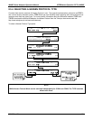
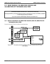
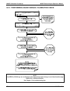
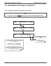
SECTION 9.2 – BASIC MANUAL CALIBRATION CHECKS AND CALIBRATION OF THE M400E ANALYZER
This section describes the procedure for checking the calibrating and calibrating the instrument with no
zero/span valves installed or if installed, not operating. It requires that zero air and span gas is inlet
through the
SAMPLE port.
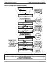
Also included are instructions for selecting the reporting range to be calibrated when the M400E
analyzer is set to operate in either the
DUAL range or AUTO range modes.
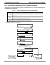
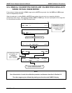
SECTION 9.3 – MANUAL CALIBRATION CHECK AND CALIBRATION WITH VALVE OPTIONS Installed
This section describes:
The procedure for checking the calibration of the instrument with zero/span valves or the izs option
installed and operating but controlled manually through the keypad on the Front Panel of the
instrument.
The procedure for calibrating of the instrument with zero/span valves and operating but controlled
manually through the keypad on the front panel of the instrument.
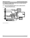
Instructions on activating the zero/span valves via the control in contact closures of the analyzers
external digital I/O.
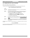
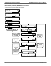
SECTION 9.4 – AUTOMATIC ZERO/SPAN Cal/Check (AutoCal)
This section describes the procedure for using the AutoCal feature of the analyzer to check or calibrate
the instrument. The AutoCal feature requires that either the zero/span valve option or the internal
zero/span (IZS) option be installed and operating.
SECTION 9.5 – O3 PHOTOMETER Electronic Calibration
This section describes how to calibrate inherent electronic offsets that may be affecting the
performance of the M400E analyzer’s internal photometer.
SECTION 9.6 – CALIBRATION THE IZS Option O3 Generator
This section describes how to check the performance of the O
3
generator that is included in the IZS
option (OPT – 51A; see Section 5.6.2) available for the M400E analyzer.
NOTE
Throughout this chapter are various diagrams showing pneumatic connections between the M400E and
various other pieces of equipment such as calibrators and zero air sources. These diagrams are only
intended to be schematic representations of these connections and do not reflect actual physical
locations of equipment and fitting location or orientation. Contact your regional EPA or other
appropriate governing agency for more detailed recommendations.
04315 Rev. C1 149