


M400E Ozone Analyzer Operator’s Manual Theory of Operation
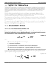
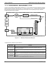
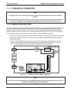
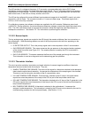
11.2.2. FLOW RATE CONTROL
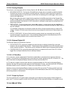
To maintain a constant flow rate of the sample gas through the instrument, the Model 400E uses a special flow
control assembly located downstream from the absorption tube and in the exhaust gas line just before the pump
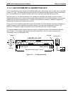
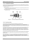
(see Figure 10-7). This assembly consists of:
A critical flow orifice.
Two o-rings: Located just before and after the critical flow orifice, the o-rings seal the gap between the walls
of assembly housing and the critical flow orifice.
A spring: Applies mechanical force needed to form the seal between the o-rings, the critical flow orifice and
the assembly housing.
Figure 11-4: Flow Control Assembly & Critical Flow Orifice
11.2.2.1. Critical Flow Orifice
The most important component of the flow control assemblies is the critical flow orifice.
Critical flow orifices are a remarkably simple way to regulate stable gas flow rates. They operate without moving
parts by taking advantage of the laws of fluid dynamics. By restricting the flow of gas though the orifice, a
pressure differential is created. This pressure differential combined with the action of the analyzer’s pump draws
the gas through the orifice.
As the pressure on the downstream side of the orifice (the pump side) continues to drop, the speed that the gas
flows though the orifice continues to rise. Once the ratio of upstream pressure to downstream pressure is
greater than 2:1, the velocity of the gas through the orifice reaches the speed of sound. As long as that ratio
stays at least 2:1 the gas flow rate is unaffected by any fluctuations, surges, or changes in downstream pressure
because such variations only travel at the speed of sound themselves and are therefore cancelled out by the
sonic shockwave at the downstream exit of the critical flow orifice.
The actual flow rate of gas through the orifice (volume of gas per unit of time), depends on the size and shape of
the aperture in the orifice. The larger the hole, the more gas molecules (moving at the speed of sound) pass
through the orifice.
With a nominal pressure of 10 in-Hg-A in the sample/reaction cell, the necessary ratio of reaction cell pressure to
pump vacuum pressure of 2:1 is exceeded and accommodating a wide range of variability in atmospheric
pressure and accounting for pump degradation. This extends the useful life of the pump. Once the pump
degrades to the point where the sample and vacuum pressures is less than 2:1, a critical flow rate can no longer
be maintained.
04315 Rev. C1 195