


M400E Ozone Analyzer Operator’s Manual General Troubleshooting & Repair of the M400E Analyzer
13.3.2.2. O
3
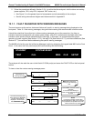
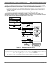
Option Status LED s
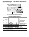
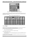
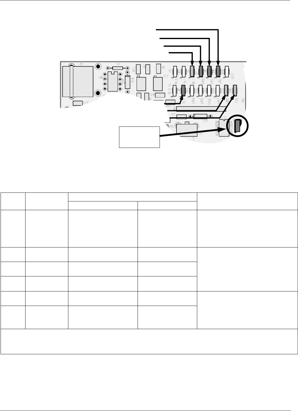
D8 (Green) – Photometer Meas/Ref Valve
D15 (Yellow) - Photometer Lamp Heater
D16 (Yellow) – IZS O
3
Generator Lamp Heater
D7 (Green) Optional Zero/Span Valve
D6 (Green ) – GPT Valve
D9 (Green) – Optional Sample/Cal Valve
D1 (RED)
Watchdog
Indicator
D2 (Yellow) Optional Metal Wool Scrubber Heater
Figure 13-3: Relay PCA Status LEDS Used for Troubleshooting
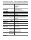
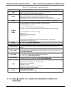
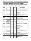
Table 13-5: Relay PCA Status LED Failure Indications
SIGNAL I/O PARAMETER
LED FUNCTION
ACTIVATED BY VIEW RESULT
DIAGNOSTIC TECHNIQUE
D2
1
Yellow
Metal Wool
Scrubber
Heater
1
O3_SCRUB_HEATER O3 SCRUB
Voltage displayed should change.
If not:
Failed Heater
Faulty Temperature Sensor
Failed AC Relay
Faulty Connectors/Wiring
D7
Green
Zero/Span Gas
Valve
3
SPAN_VALVE
N/A
D8
Green
Measure/Ref
Valve
PHOTO_REF_VALVE
N/A
D9
Green
Sample/Cal
Gas Valve
2
CAL_VALVE
N/A
Valve should audibly change states.
If not:
Failed Valve
Failed Relay Drive IC on Relay PCA
Failed Relay PCA
Faulty +12 VDC Supply (PS2)
Faulty Connectors/Wiring
D15
Yellow
Photometer UV
Lamp Heater
_PHOTO_LAMP_HEATER PHOTO_LAMP
D16
2
Green
IZS O
3
Generator UV
Lamp Heater
O3_GEN_HEATER O3 GEN TEMP
Voltage displayed should change.
If not:
Failed Heater
Faulty Temperature Sensor
Failed AC Relay
Faulty Connectors/Wiring
1
Only applies on analyzers with metal wool scrubber installed.
2
Only applies on analyzers with IZS options installed.
3
Only apllies to instruments with calibrtn valve options installed.
04315 Rev. C1 241