


Section 18 Serial Sound Interface
R01UH0134EJ0400 Rev. 4.00 Page 925 of 2108
Sep 24, 2014
SH7262 Group, SH7264 Group
MSB LSB
System word 2
Data
word 1
MSB LSB MSB LSB MSB LSB MSB LSB MSB LSB MSB LSB MSB LSB
Data
word 2
Data
word 3
Data
word 4
Data
word 5
Data
word 6
Data
word 7
Data
word 8
Padding
System word 1
Padding
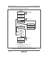
SSIWS
SSIDATA
SSISCK
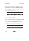
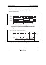
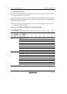
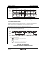
SCKP = 0, SWSP = 0, DEL = 0, CHNL = 11, SPDP = 0, SDTA = 1
System word length = data word length × 4
Figure 18.9 Multi-Channel Format (8 Channels; Transmitting and Receiving in
the Order of Serial Data and Padding Bits; with Padding)
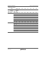
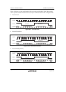
(9) Bit Setting Configuration Format
Several more configuration bits in non-compressed mode are shown below. These bits are not
mutually exclusive, but some combinations may not be useful for any other device.
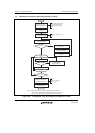
These configuration bits are described below with reference to figure 18.10.
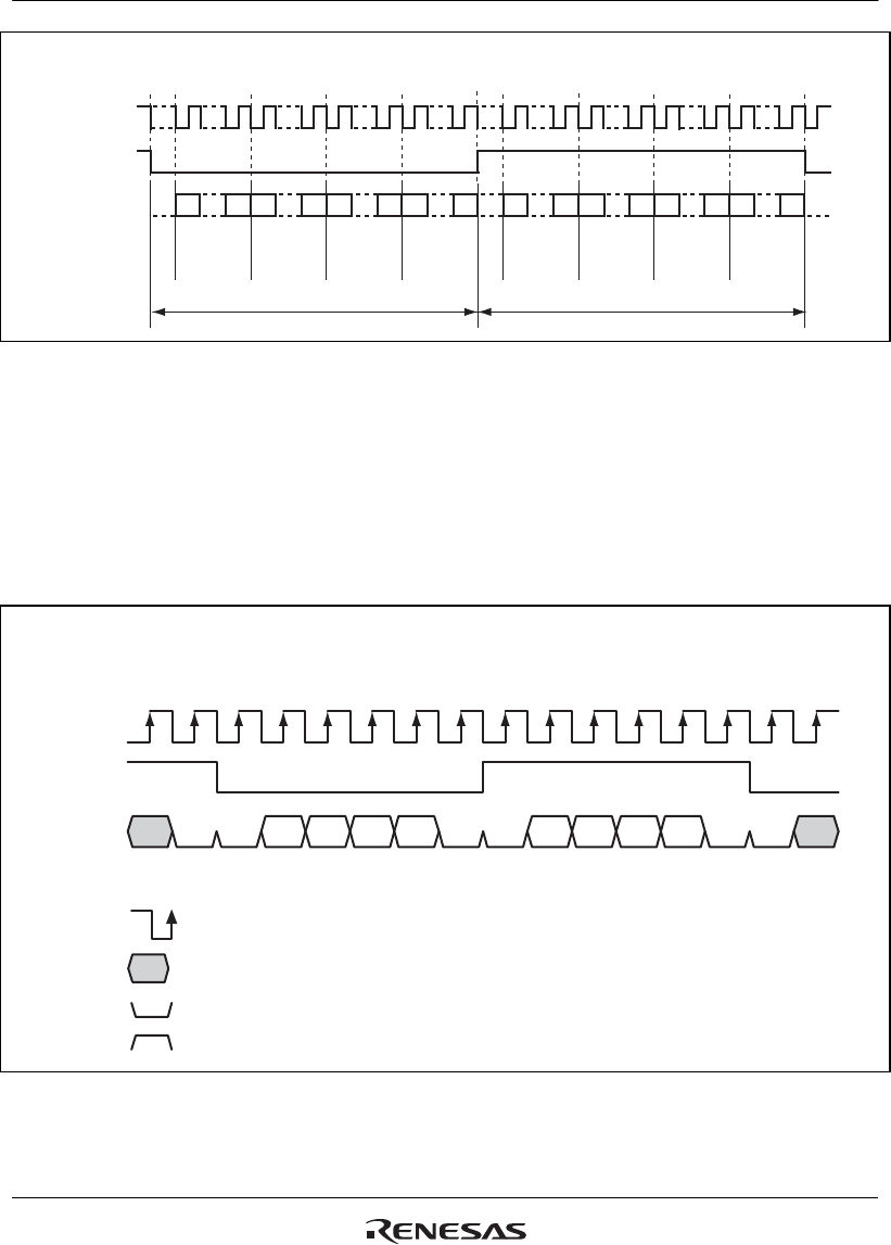
SSISCK
SSIWS
SSIDATA
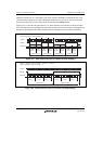
Key for this and following diagrams:
0000 00
means a low level on the serial bus (padding or mute)
0
means a high level on the serial bus (padding)
1
Arrow head indicates sampling point of receiver
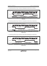
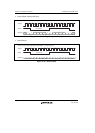
Bit n in SSITDR
TDn
1st channel 2nd channel
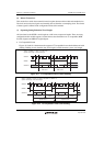
TD28 TD31TD31 TD30 TD29 TD28 TD31 TD30 TD29 TD28
SWL = 6 bits (not attainable in SSI module, demonstration only)
DWL = 4 bits (not attainable in SSI module, demonstration only)
CHNL = 00, SCKP = 0, SWSP = 0, SPDP = 0, SDTA = 0, PDTA = 0, DEL = 0, MUEN = 0
4-bit data samples continuously written to SSITDR are transmitted onto the serial audio bus.
Figure 18.10 Basic Sample Format
(Transmit Mode with Example System/Data Word Length)