


Section 9 Bus State Controller
Page 368 of 2108 R01UH0134EJ0400 Rev. 4.00
Sep 24, 2014
SH7262 Group, SH7264 Group
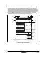
The write buffer of the bus state controller functions in the same way for an access by a bus master
other than the CPU such as the direct memory access controller. Accordingly, to perform dual
address DMA transfers, the next read cycle is initiated before the previous write cycle is
completed. Note, however, that if both the DMA source and destination addresses exist in external
memory space, the next read cycle will not be initiated until the previous write cycle is completed.
Changing the registers in this module while the write buffer is operating may disrupt correct write
access. Therefore, do not change the registers in this module immediately after a write access. If
this change becomes necessary, do it after executing a dummy read of the write data.
(3) On-Chip Peripheral Module Access
To access an on-chip module register, two or more peripheral module clock (P) cycles are
required. Care must be taken in system design.
When the CPU writes data to the internal peripheral registers, the CPU performs the succeeding
instructions without waiting for the completion of writing to registers.
For example, a case is described here in which the system is transferring to the software standby
mode for power savings. To make this transition, the SLEEP instruction must be performed after
setting the STBY bit in the STBCR1 register to 1. However a dummy read of the STBCR1 register
is required before executing the SLEEP instruction. If a dummy read is omitted, the CPU executes
the SLEEP instruction before the STBY bit is set to 1, thus the system enters sleep mode not
software standby mode. A dummy read of the STBCR1 register is indispensable to complete
writing to the STBY bit.
To reflect the change by internal peripheral registers while performing the succeeding instructions,
execute a dummy read of registers to which write instruction is given and then perform the
succeeding instructions.
(4) External Flash Memory Access by NAND Flash Memory Controller
In this product, a part of the external data bus is used also as data bus for the NAND flash memory
controller. The use of the data bus is controlled by the NAND flash memory controller. Memory
access by the NAND flash memory controller is started after the preceding access to the external
device by this module is completed. If an access to the external device by this module occurs
during the access by the NAND flash memory controller, it must wait until the completion of the
access by the NAND flash memory controller.