


Section 20 Controller Area Network
R01UH0134EJ0400 Rev. 4.00 Page 983 of 2108
Sep 24, 2014
SH7262 Group, SH7264 Group
20.2 Architecture
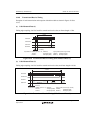
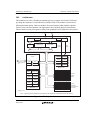
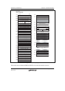
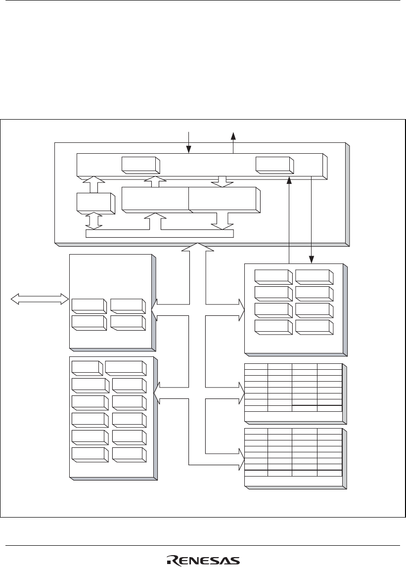
This module device offers a flexible and sophisticated way to organise and control CAN frames,
providing the compliance to CAN2.0B Active and ISO-11898-1. The module is formed from 5
different functional entities. These are the Micro Processor Interface (MPI), Mailbox, Mailbox
Control, Timer, and CAN Interface. The figure below shows the block diagram of the Module.
The bus interface timing is designed according to the peripheral bus I/F required for each product.
IRR
GSR
MCR
IMR
Mailbox8
Mailbox9
Mailbox10
Mailbox11
Mailbox12
Mailbox13
Mailbox14
Mailbox15
Mailbox16
Mailbox17
Mailbox18
Mailbox19
Mailbox20
Mailbox21
Mailbox22
Mailbox23
Mailbox24
Mailbox25
Mailbox26
Mailbox27
Mailbox28
Mailbox29
Mailbox30
Mailbox31
Mailbox0
Mailbox1
Mailbox2
Mailbox3
Mailbox4
Mailbox5
Mailbox6
Mailbox7
TTCR0
CMAX_TEW
RFTROFF
TSR
CCR
TCNTR
CYCTR
RFMK
TCMR0
TCMR1
TCMR2
TTTSEL
CTxnCRxn
TXPR
TXCR
RXPR
TXACK
ABACK
MBIMR
TEC
REC
CAN Interface
Can Core
Control
Signals
Status
Signals
RFPR
UMSR
BCR
Transmit Buffer Receive Buffer
Mailbox Control
32-bit internal Bus System
Mailbox 0 to 31 (RAM)
Mailbox 0 to 31 (register)
control0
LAFM
DATA
control1
Timestamp
Tx-Trigger Time
TT control
16-bit peripheral
bus
[Legend] n = 0, 1
16-bit Timer
Micro Processor
Interface
Note: Longword (32-bit) accesses are converted into two consecutive word accesses by the bus interface.
Figure 20.1 This Module Architecture