


Section 11 Multi-Function Timer Pulse Unit 2
Page 524 of 2108 R01UH0134EJ0400 Rev. 4.00
Sep 24, 2014
SH7262 Group, SH7264 Group
11.4.5 PWM Modes
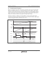
In PWM mode, PWM waveforms are output from the output pins. The output level can be selected
as 0, 1, or toggle output in response to a compare match of each TGR.
TGR registers settings can be used to output a PWM waveform in the range of 0% to 100% duty.
Designating TGR compare match as the counter clearing source enables the period to be set in that
register. All channels can be designated for PWM mode independently. Synchronous operation is
also possible.
There are two PWM modes, as described below.
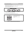
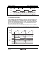
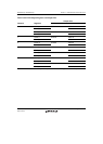
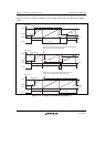
PWM mode 1
PWM output is generated from the TIOCA and TIOCC pins by pairing TGRA with TGRB and
TGRC with TGRD. The output specified by bits IOA0 to IOA3 and IOC0 to IOC3 in TIOR is
output from the TIOCA and TIOCC pins at compare matches A and C, and the output
specified by bits IOB0 to IOB3 and IOD0 to IOD3 in TIOR is output at compare matches B
and D. The initial output value is the value set in TGRA or TGRC. If the set values of paired
TGRs are identical, the output value does not change when a compare match occurs.
In PWM mode 1, a maximum 8-phase PWM output is possible.
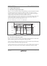
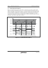
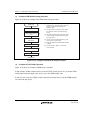
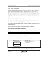
PWM mode 2
PWM output is generated using one TGR as the cycle register and the others as duty registers.
The output specified in TIOR is performed by means of compare matches. Upon counter
clearing by a cycle register compare match, the output value of each pin is the initial value set
in TIOR. If the set values of the cycle and duty registers are identical, the output value does
not change when a compare match occurs.
In PWM mode 2, a maximum 8-phase PWM output is possible in combination use with
synchronous operation.
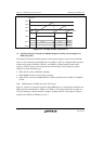
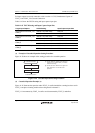
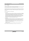
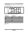
The correspondence between PWM output pins and registers is shown in table 11.44.