


Section 11 Multi-Function Timer Pulse Unit 2
R01UH0134EJ0400 Rev. 4.00 Page 529 of 2108
Sep 24, 2014
SH7262 Group, SH7264 Group
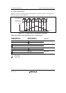
11.4.6 Phase Counting Mode
In phase counting mode, the phase difference between two external clock inputs is detected and
TCNT is incremented/decremented accordingly. This mode can be set for channels 1 and 2.
When phase counting mode is set, an external clock is selected as the counter input clock and
TCNT operates as an up/down-counter regardless of the setting of bits TPSC0 to TPSC2 and bits
CKEG0 and CKEG1 in TCR. However, the functions of bits CCLR0 and CCLR1 in TCR, and of
TIOR, TIER, and TGR, are valid, and input capture/compare match and interrupt functions can be
used.
This can be used for two-phase encoder pulse input.
If overflow occurs when TCNT is counting up, the TCFV flag in TSR is set; if underflow occurs
when TCNT is counting down, the TCFU flag is set.
The TCFD bit in TSR is the count direction flag. Reading the TCFD flag reveals whether TCNT is
counting up or down.
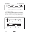
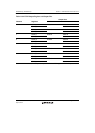
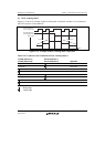
Table 11.45 shows the correspondence between external clock pins and channels.
Table 11.45 Phase Counting Mode Clock Input Pins
External Clock Pins
Channels A-Phase B-Phase
When channel 1 is set to phase counting mode TCLKA TCLKB
When channel 2 is set to phase counting mode TCLKC TCLKD
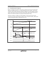
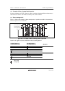
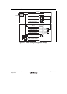
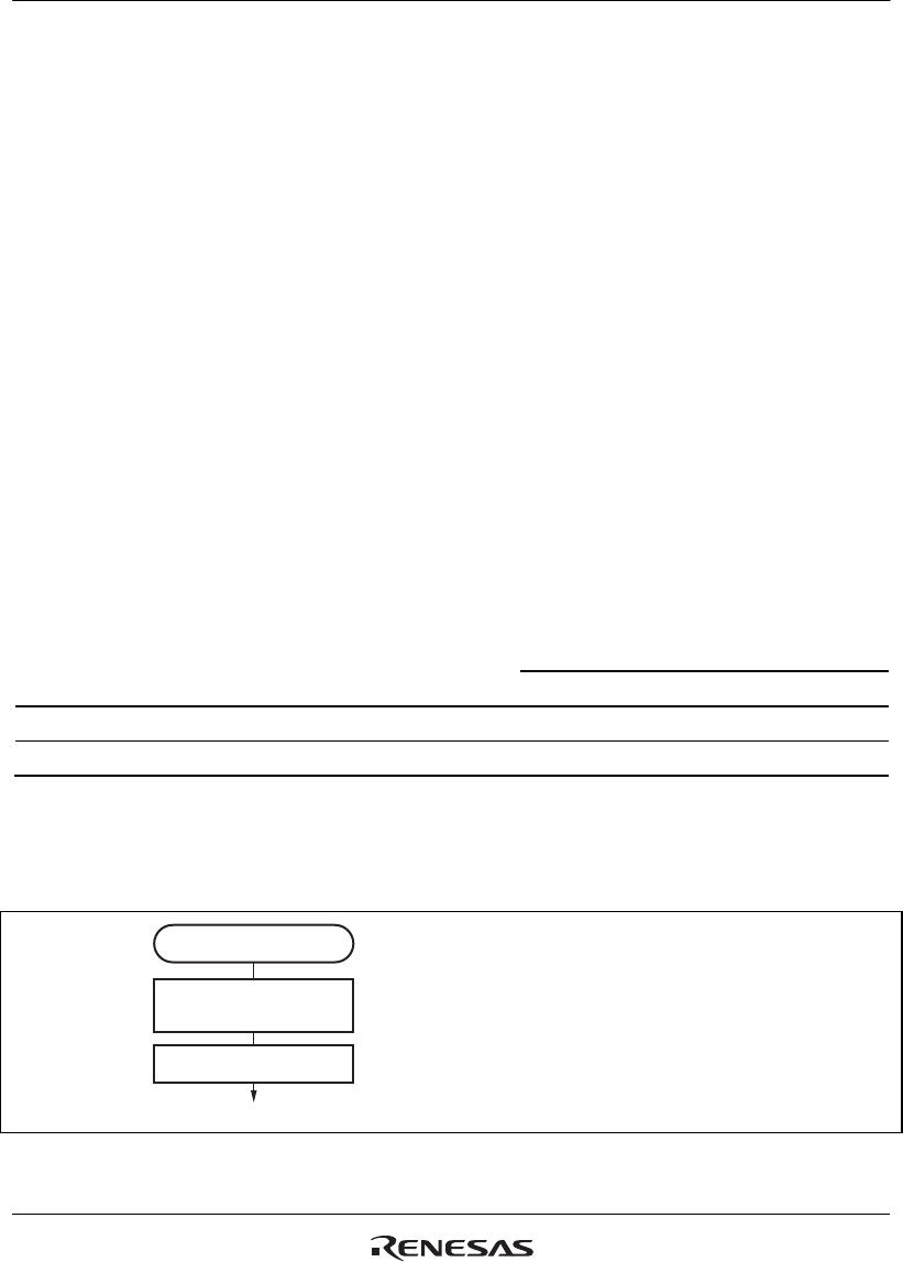
(1) Example of Phase Counting Mode Setting Procedure
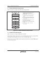
Figure 11.29 shows an example of the phase counting mode setting procedure.
Phase counting mode
Select phase counting
mode
Start count
<Phase counting mode>
[1]
[2]
[1] Select phase counting mode with bits
MD3 to MD0 in TMDR.
[2] Set the CST bit in TSTR to 1 to start
the count operation.
Figure 11.29 Example of Phase Counting Mode Setting Procedure