


Section 11 Multi-Function Timer Pulse Unit 2
R01UH0134EJ0400 Rev. 4.00 Page 639 of 2108
Sep 24, 2014
SH7262 Group, SH7264 Group
(21) Operation when Error Occurs during Complementary PWM Mode Operation, and
Operation is Restarted in Normal Mode
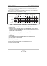
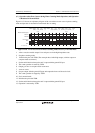
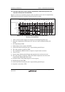
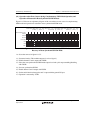
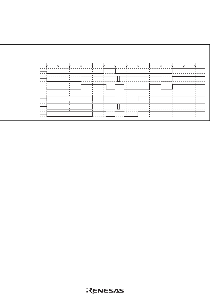
Figure 11.135 shows an explanatory diagram of the case where an error occurs in complementary
PWM mode and operation is restarted in normal mode after re-setting.
1
RESET
2
TOCR
3
TMDR
(CPWM)
5
PFC
(MTU2)
4
TOER
(1)
6
TSTR
(1)
7
Match
8
Error
occurs
9
PFC
(PORT)
10
TSTR
(0)
11
TMDR
(normal)
12
TIOR
(1 init
0 out)
13
PFC
(MTU2)
14
TSTR
(1)
MTU2 module output
TIOC3A
TIOC3B
TIOC3D
Port output
PE9
PE8
PE11
High-Z
High-Z
High-Z
Figure 11.135 Error Occurrence in Complementary PWM Mode,
Recovery in Normal Mode
1. After a reset, the module output is low and ports are in the high-impedance state.
2. Select the complementary PWM output level and cyclic output enabling/disabling with
TOCR.
3. Set complementary PWM.
4. Enable channel 3 and 4 output with TOER.
5. Set the multi-function timer pulse unit 2 output with the general I/O port.
6. The count operation is started by TSTR.
7. The complementary PWM waveform is output on compare-match occurrence.
8. An error occurs.
9. Set port output with the general I/O port and output the inverse of the active level.
10. The count operation is stopped by TSTR. (This module outputs the same value as the
complementary PWM output initial value.)
11. Set normal mode. (This module outputs a low-level signal.)
12. Initialize the pins with TIOR.
13. Set the multi-function timer pulse unit 2 output with the general I/O port.
14. Operation is restarted by TSTR.