


Section 11 Multi-Function Timer Pulse Unit 2
R01UH0134EJ0400 Rev. 4.00 Page 537 of 2108
Sep 24, 2014
SH7262 Group, SH7264 Group
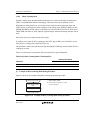
(1) Procedure for Selecting the Reset-Synchronized PWM Mode
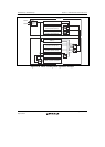
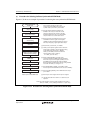
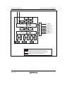
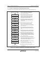
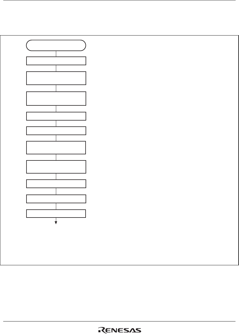
Figure 11.35 shows an example of procedure for selecting the reset synchronized PWM mode.
Stop counting
Select counter clock and
counter clear source
Set TGR
Reset-synchronized
PWM mode
Brushless DC motor
control setting
Set TCNT
Enable waveform output
Set reset-synchronized
PWM mode
PWM cycle output enabling,
PWM output level setting
Start count operation
Reset-synchronized PWM mode
[1] Clear the CST3 and CST4 bits in the TSTR
to 0 to halt the counting of TCNT. The
reset-synchronized PWM mode must be set
up while TCNT_3 and TCNT_4 are halted.
[2] Set bits TPSC2-TPSC0 and CKEG1 and
CKEG0 in the TCR_3 to select the counter
clock and clock edge for channel 3. Set bits
CCLR2-CCLR0 in the TCR_3 to select TGRA
compare-match as a counter clear source.
[3] When performing brushless DC motor control,
set bit BDC in the timer gate control register
(TGCR) and set the feedback signal input source
and output chopping or gate signal direct output.
[4] Reset TCNT_3 and TCNT_4 to H'0000.
[5] TGRA_3 is the period register. Set the waveform
period value in TGRA_3. Set the transition timing
of the PWM output waveforms in TGRB_3,
TGRA_4, and TGRB_4. Set times within the
compare-match range of TCNT_3.
X ≤ TGRA_3 (X: set value).
[6] Select enabling/disabling of toggle output
synchronized with the PMW cycle using bit PSYE
in the timer output control register (TOCR), and set
the PWM output level with bits OLSP and OLSN.
When specifying the PWM output level by using TOLBR
as a buffer for TOCR_2, see figure 11.3.
[7] Set bits MD3-MD0 in TMDR_3 to B'1000 to select
the reset-synchronized PWM mode. Do not set to TMDR_4.
[8] Set the enabling/disabling of the PWM waveform output
pin in TOER.
[9] Set the port control register and the port I/O register.
[10] Set the CST3 bit in the TSTR to 1 to start the count
operation.
[1]
[2]
[3]
[4]
[5]
[6]
[7]
[8]
PFC setting
[9]
[10]
Note: The output waveform starts to toggle operation at the point of
TCNT_3 = TGRA_3 = X by setting X = TGRA, i.e., cycle = duty.
Figure 11.35 Procedure for Selecting Reset-Synchronized PWM Mode