


Section 5 Clock Pulse Generator
R01UH0134EJ0400 Rev. 4.00 Page 127 of 2108
Sep 24, 2014
SH7262 Group, SH7264 Group
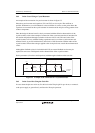
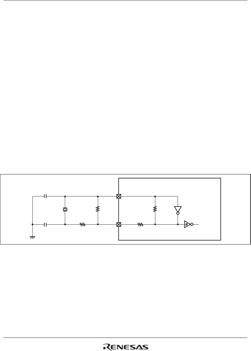
5.6.2 In the Case of Using a Crystal Resonator
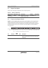
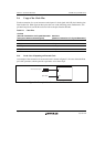
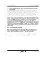
An example of the connection of crystal resonator is shown in figure 5.3.
Place the crystal resonator and capacitors (CL1 and CL2) as close to pins Xin and Xout as
possible. Furthermore, to avoid inductance so that oscillation is correct, use the points where the
capacitors are connected to the crystal resonator in common and do not place wiring patterns close
to these components.
Since the design of the user board is closely connected with the effective characteristics of the
crystal resonator, refer to the example of connection of the crystal resonator that is introduced in
this section and perform thorough evaluation on the user side as well. The rated value of the
crystal resonator will vary with the floating capacitances and so on of the crystal resonator and
mounted circuit, so proceed with decisions on the basis of full discussions with the maker of the
crystal resonator. Ensure that voltages applied to the clock pins do not exceed the maximum rated
values.
Although the feedback resistor is included in this LSI, an external feedback resistor may be
required in some cases. This depends on the characteristics of the crystal resonator.
Set the parameters (of resistors and capacitors) with thorough evaluation on the user side.
Xin
Xout
R
IF
R
ID
R
OF
R
OD
This LSI
CL1
CL2
To internal
sections
Crystal
resonator
Figure 5.3 Example of the Connection of a Crystal Resonator
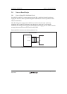
5.6.3 In the Case of Not Using the Clock Pin
In cases where the pins are not in use, fix the level on the Xin pin (pull it up or down, or connect it
to the power-supply or ground level), and leave the Xout pin open state.