


Page 2084 of 2108 R01UH0134EJ0400 Rev. 4.00
Sep 24, 2014
Item Page Revision (See Manual for Details)
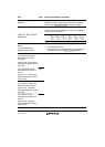
26.4.4 FIFO Buffer Memory
(2) FIFO Port Functions
(a) FIFO Port Selection
1518 Description amended
Also, the bus width to be accessed should be selected
using the MBW bit. The buffer memory access direction
conforms to the DIR bit in PIPE CFG. The ISEL bit
determines this only for the DCP.
26.4.5 Control Transfers
(DCP)
(2) Control Transfers when
the Function Controller
Function is Selected
(b) Data Stage
1526 Description deleted
A transaction is executed by setting the PID bits in the
DCPCTR register to BUF. The BRDY interrupt or the
BEMP interrupt can be used to detect the end of data
transfer. Use the BRDY interrupt to detect the end of
control write transfers and the BEMP interrupt to detect the
end of control read transfers.
With control write transfers during high-speed operation,
the NYET handshake response is carried out based on the
state of the buffer memory.
26.4.8 Isochronous
Transfers (PIPE1 and PIPE2)
(3) Interval Counter
(c) Interval Counting and
Transfer Control when the
Function Controller Function
is Selected
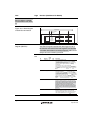
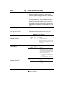
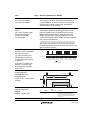
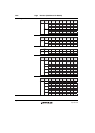
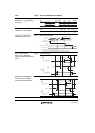
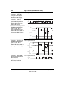
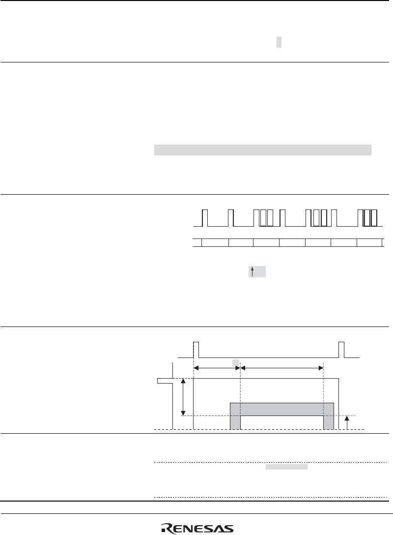
Figure 26.19 Relationship
between () Frames and
Expected Token Reception
when IITV = 1
1539 Figure amended
Interval counter started
USB bus
PID bit setting
NAK
S
O
F
S
O
F
S
O
F
S
O
F
S
O
F
S
O
F
S
O
F
FUBFUB FUBFUBFUBFUB
To ke n
reception
is waited
To ke n
reception
is waited
D
A
T
A
0
D
A
T
A
0
D
A
T
A
0
O
U
T
O
U
T
O
U
T
To ke n
reception
is waited
To ke n
reception
is not waited
To ke n
reception
is not waited
To ke n
reception
is not waited
To ke n
reception
is not waited
To ke n
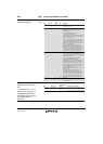
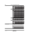
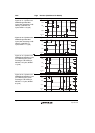
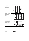
27.7.24 Control Area Start
Position Registers
(GROPEDPHV1 and
GROPEDPHV2)
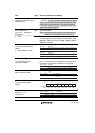
Figure 27.22 Control Area
Settings
1605 Figure amended
Reference Hsync
GROPEDPH + 10
GROPEW
Graphics image area
GROPEDPV + 1
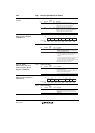
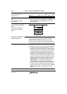
27.7.35 Horizontal Sync
Signal Timing Control
Register
(PANEL_HSYNC_TIM)
1619 Table amended
Bit Bit Name
Initial
Value R/W Description
26 to 16 HSYNC_START
[10:0]
H'000 R/W These bits specify in number of
panel clock cycles the interval between the
reference horizontal sync signal and the point
where the horizontal sync signal (HSYNC) for
panel is set to 1.