


Section 23 CD-ROM Decoder
Page 1194 of 2108 R01UH0134EJ0400 Rev. 4.00
Sep 24, 2014
SH7262 Group, SH7264 Group
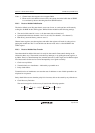
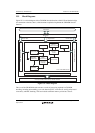
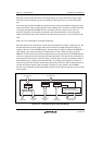
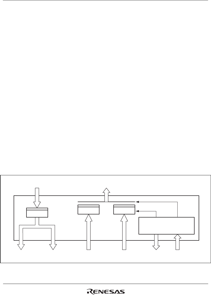
Input data come from the internal bus and output data go out via the internal bus along a single
line each, but the bus bridge logic sets up branches for the register access port and stream data
port.
The stream data from the CD-DSP are transferred via the serial sound interface to the stream data
input control block. They are then subjected to descrambling, ECC correction, and EDC checking
as they pass through the CD-ROM decoder. After these processes, data from one sector are
obtained. The data are subsequently transferred to the stream-data buffer via the stream-data
output control block. Data can be transferred by either the direct memory access controller or the
CPU.
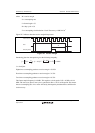
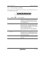
Figure 23.3 is a block diagram of the bus-bridge logic.
Since the input stream is transferred over the serial sound interface, transfer is relatively slow. On
the other hand, data from the output stream can be transferred at high speeds because they are
already in the core of the CD-ROM decoder. Since the data for output are buffered in SDRAM or
other memory, they must be transferred at high speeds in order to reduce the busy rate of the
SDRAM. For this reason, the data for the output stream are read out before the CD-ROM decoder
receives an output stream data read request from the internal bus. This allows the accumulation of
streaming data in the registers of the bus bridge, so that the data are ready for immediate output to
the internal bus upon a request from the internal bus. Accordingly, the reception of a request to
read from registers other than the stream-data registers after the stream data has already been read
out and stored in the register of the bus bridge is possible. To cope with this, the CD-ROM
decoder is provided with separate intermediary registers for the output stream-data register and the
other registers.
Input data from
the internal bus
Input
stream data
Output
stream data
Register data
(write)
Register data
(read)
Output stream-data
control signal
Buffer control signal for
the output stream-data section
Data for output to
the internal bus
Figure 23.3 Schematic Diagram of the Bus Bridge