


Section 4 Boot Mode
Page 110 of 2108 R01UH0134EJ0400 Rev. 4.00
Sep 24, 2014
SH7262 Group, SH7264 Group
4.3 Operation
4.3.1 Boot Mode 0
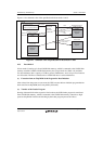
In boot mode 0, this LSI is booted from the memory connected to the CS0 space. In this mode,
this LSI operates as follows:
After the power-on reset is canceled, the initial value (execution start address) of the program
counter (PC) and the initial value of the stack pointer (SP) are fetched from the exception handling
vector table located in the memory connected to the CS0 space, then program execution is started.
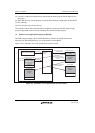
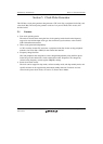
4.3.2 Boot Modes 1 and 3
In boot modes 1 and 3, booting up is from serial flash memory, which is connected to channel 0 of
the Renesas serial peripheral interface. The flow of initiation in boot mode is as described below.
(1) Execution from on-Chip ROM of the Program for Boot Initiation
After release from the power-on reset state, the CPU executes the boot initiation program that has
been stored in on-chip ROM (and is not publicly disclosed).
(2) Transfer of the Loader Program
Starting with transfer from the respective first locations, the 8-KB loader program is transferred
from serial flash memory, which is connected to channel 0 of the Renesas serial peripheral
interface, to high-speed on-chip RAM.
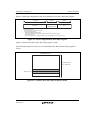
Transfer proceeds at 1/2 of the rate of the bus clock (B) in boot mode 1 and at 1/4 of the rate of
the bus clock in boot mode 3. Decide on the boot mode in accord with the connected serial flash
memory.
Once transfer of the loader program has been completed, execution by the CPU jumps to high-
speed on-chip RAM so that it can start executing the transferred loader program.
(3) Transfer of an Application Program (as Desired)
The loader program employs the Renesas serial peripheral interface to transfer the data to be
deployed from serial flash memory to on-chip RAM or external RAM.