


Section 7 Interrupt Controller
R01UH0134EJ0400 Rev. 4.00 Page 195 of 2108
Sep 24, 2014
SH7262 Group, SH7264 Group
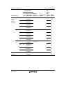
7.7 Interrupt Response Time
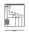
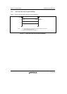
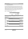
Table 7.5 lists the interrupt response time, which is the time from the occurrence of an interrupt
request until the interrupt exception handling starts and fetching of the first instruction in the
exception service routine begins. The interrupt processing operations differ in the cases when
banking is disabled, when banking is enabled without register bank overflow, and when banking is
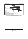
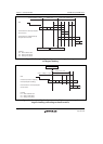
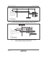
enabled with register bank overflow. Figures 7.4 and 7.5 show examples of pipeline operation
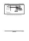
when banking is disabled. Figures 7.6 and 7.7 show examples of pipeline operation when banking
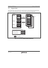
is enabled without register bank overflow. Figures 7.8 and 7.9 show examples of pipeline
operation when banking is enabled with register bank overflow.
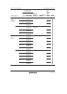
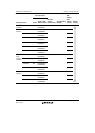
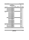
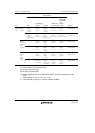
Table 7.5 Interrupt Response Time
Item
Number of States
Remarks
NMI
User
Debugging
Interface
IRQ, PINT
USB 2.0
host/
function
module
Peripheral
Module
(Other than
USB 2.0
host/
function
module)
Time from occurrence of interrupt
request until interrupt controller
identifies priority, compares it with
mask bits in SR, and sends interrupt
request signal to CPU
2 Icyc
2 Bcyc +
1 Pcyc
2 Icyc
1 Pcyc
2 Icyc
3 Bcyc +
1 Pcyc
2 Icyc
4 Bcyc
2 Icyc
2 Bcyc
Time from
input of
interrupt
request signal
to CPU until
sequence
currently being
executed is
completed,
interrupt
exception
handling starts,
and first
instruction in
interrupt
exception
service routine
is fetched
No register
banking
Min. 3 Icyc + m1 + m2 Min. is when the interrupt
wait time is zero.
Max. is when a higher-
priority interrupt request has
occurred during interrupt
exception handling.
Max. 4 Icyc + 2(m1 + m2) + m3
Register
banking
without
register
bank
overflow
Min. 3 Icyc + m1 + m2 Min. is when the interrupt
wait time is zero.
Max. is when an interrupt
request has occurred during
execution of the RESBANK
instruction.
Max. 12 Icyc + m1 + m2
Register
banking
with
register
bank
overflow
Min. 3 Icyc + m1 + m2 Min. is when the interrupt
wait time is zero.
Max. is when an interrupt
request has occurred during
execution of the RESBANK
instruction.
Max. 3 Icyc + m1 + m2 + 19(m4)