Section 20 Controller Area Network
Page 1056 of 2108 R01UH0134EJ0400 Rev. 4.00
Sep 24, 2014
SH7262 Group, SH7264 Group
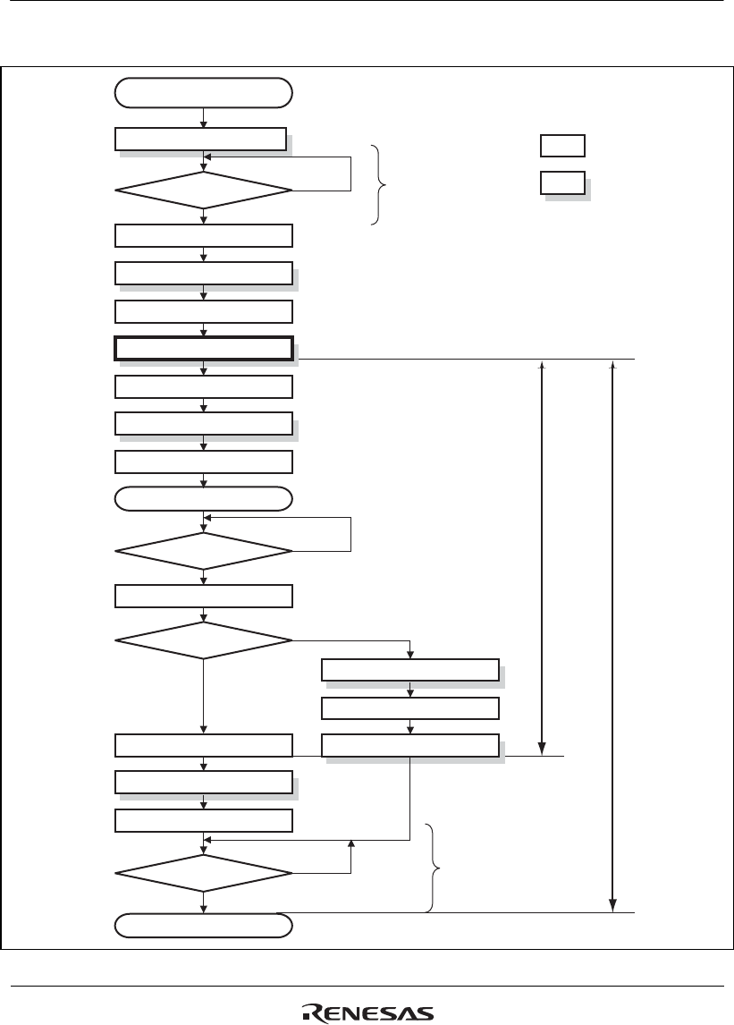
The following diagram shows the flow to follow to move this module into sleep mode.
Sleep Mode
Transmission/Reception Mode
GSR[4] = 1
User monitor
User monitor
Yes
IRR[0] = 1
Write MCR[1] = 1
Write IRR[0] = 1
: Hardware operation
: Manual operation
IRR[0] = 1
IRR[12] = 1
Write IRR[0] = 1
IRR[0] = 0
IRR[0] = 0
MCR[5] = 0
Write IRR[12] = 1
IRR[12] = 0
Write MCR[1] = 0 & MCR[5] = 1
Halt Request
Sleep Request
Write IRR[12] = 1
IRR[12] = 0
Write MCR[5] = 0
No
CAN Bus Activity
Yes
Sleep Mode
Sequence flow
No
GSR4 = 0
Yes
No
MCR[7] = 1
Yes
No
CLK is
STOP
Only MCR, GSR,
IRR, IMR can be
accessed.


