


Section 26 USB 2.0 Host/Function Module
Page 1524 of 2108 R01UH0134EJ0400 Rev. 4.00
Sep 24, 2014
SH7262 Group, SH7264 Group
26.4.5 Control Transfers (DCP)
Data transfers of the data stage of control transfers are done using the default control pipe (DCP).
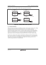
The DCP buffer memory is a 256-byte single buffer, and is a fixed area that is shared for both
control reading and control writing. The buffer memory can be accessed through the CFIFO port.
(1) Control Transfers when the Host Controller Function is Selected
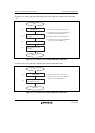
(a) Setup Stage
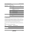
USQREQ, USBVAL, USBINDX, and USBLENG are the registers that are used to transmit a USB
request for setup transactions. Writing setup packet data to the registers and writing 1 to the
SUREQ bit in DCPCTR transmits the specified data for setup transactions. Upon completion of
transactions, the SUREQ bit is cleared to 0. The above USB request registers should not be
modified while SUREQ = 1. The device address for setup transactions is specified using the
DEVSEL bits in DCPMAXP.
When the data for setup transactions has been sent, a SIGN or SACK interrupt request is generated
according to the response received from the peripheral device (SIGN1 or SACK bits in INTSTS1),
by means of which the result of the setup transactions can be confirmed.
A data packet of DATA0 (USB request) is transmitted as the data packet for the setup transactions
regardless of the setting of the SQMON bit in DCPCTR.
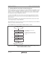
(b) Data Stage
Data transfers are done using the DCP buffer memory.
The access direction of the DCP buffer memory should be specified using the ISEL bit in
CFIFOSEL. Also specify the transfer direction using the DIR bit in the DCPCFG register.
For the first data packet of the data stage, the data PID must be transferred as DATA1. Transaction
is done by setting the data PID = DATA1 and the PID bit = BUF using the SQSET bit in
DCPCTR. Completion of data transfer is detected using the BRDY or BEMP interrupts.
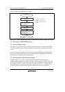
Setting continuous transfer mode allows data transfers over multiple packets. Note that when
continuous transfer mode is set for the receiving direction, the BRDY interrupt is not generated
until the buffer becomes full or a short packet is received (the integer multiple of the maximum
packet size, and less than 256 bytes).
For control write transfers, when the number of data bytes to be sent is the integer multiple of the
maximum packet size, a zero-length packet must be controlled to be sent at the end.