


Section 9 Bus State Controller
Page 356 of 2108 R01UH0134EJ0400 Rev. 4.00
Sep 24, 2014
SH7262 Group, SH7264 Group
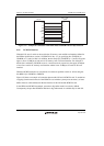
9.5.11 Wait between Access Cycles
As the operating frequency of LSIs becomes higher, the off-operation of the data buffer often
collides with the next data access when the read operation from devices with slow access speed is
completed. As a result of these collisions, the reliability of the device is low and malfunctions may
occur. A function that avoids data collisions by inserting idle (wait) cycles between continuous
access cycles has been newly added.
The number of wait cycles between access cycles can be set by the WM bit in CSnWCR, bits
IWW2 to IWW0, IWRWD2 to IWRWD0, IWRWS2 to IWRWS0, IWRRD2 to IWRRD0, and
IWRRS2 to IWRRS 0 in CSnBCR, and bits DMAIW2 to DMAIW0 and DMAIWA in CMNCR.
The conditions for setting the idle cycles between access cycles are shown below.
1. Continuous access cycles are write-read or write-write
2. Continuous access cycles are read-write for different spaces
3. Continuous access cycles are read-write for the same space
4. Continuous access cycles are read-read for different spaces
5. Continuous access cycles are read-read for the same space
6. Data output from an external device caused by DMA single address transfer is followed by
data output from another device that includes this LSI (DMAIWA = 0)
7. Data output from an external device caused by DMA single address transfer is followed by any
type of access (DMAIWA = 1)
For the specification of the number of idle cycles between access cycles described above, refer to
the description of each register.
Besides the idle cycles between access cycles specified by the registers, idle cycles must be
inserted to interface with the internal bus or to obtain the minimum pulse width for a multiplexed
pin (WEn). The following gives detailed information about the idle cycles and describes how to
estimate the number of idle cycles.
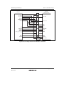
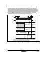
The number of idle cycles on the external bus from CSn negation to CSn or CSm assertion is
described below. Here, CSn and CSm also include CE2A and CE2B for PCMCIA.
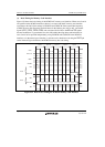
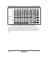
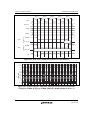
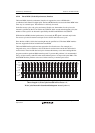
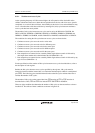
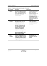
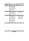
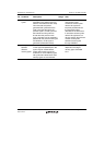
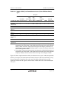
There are eight conditions that determine the number of idle cycles on the external bus as shown
in table 9.16. The effects of these conditions are shown in figure 9.45.