


Section 33 Power-Down Modes
R01UH0134EJ0400 Rev. 4.00 Page 1801 of 2108
Sep 24, 2014
SH7262 Group, SH7264 Group
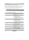
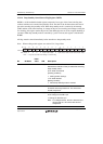
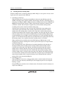
33.2.18 Deep Standby Cancel Edge Select Register (DSESR)
DSESR is a 16-bit readable/writable register that consists of the bits for selecting an edge to be
detected for the pin specified as a deep standby cancel source with DSSSR. This register setting is
always valid for canceling deep standby, regardless of the interrupt controller setting.
Note: When writing to this register, see section 33.4, Usage Notes.
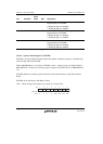
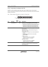
1514131211109876543210
Bit:
Initial value:
R/W:
0000000000000000
R R R R R R/W R/W R/W R R R/W R/W R/W R/W R/W R/W
- - - - - PG11E PG10E NMIE - - PC8E PC7E PC6E PC5E PJ1EPJ3E
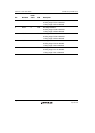
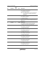
Bit Bit Name
Initial
Value R/W Description
15 to 11 All 0 R Reserved
These bits are always read as 0. The write value
should always be 0.
10 PG11E 0 R/W PG11 Edge Detection
0: Falling edge of PG11 is detected.
1: Rising edge of PG11 is detected.
Note: For 1-Mbyte version, this bit is reserved and
always read as 0. The write value should
always be 0.
9 PG10E 0 R/W PG10 Edge Detection
0: Falling edge of PG10 is detected.
1: Rising edge of PG10 is detected.
Note: For 1-Mbyte version, this bit is reserved and
always read as 0. The write value should
always be 0.
8 NMIE 0 R/W NMI Edge Detection
0: Falling edge of NMI is detected.
1: Rising edge of NMI is detected.
7, 6 All 0 R Reserved
These bits are always read as 0. The write value
should always be 0.
5 PC8E 0 R/W PC8 Edge Detection
0: Falling edge of PC8 is detected.
1: Rising edge of PC8 is detected.