


Where to go next 35
Model 1001MC Operations Guide 2 • Hardware installation
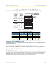
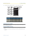
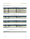
Ethernet LED indicators
The Ethernet LEDs convey transmit and receive data activity as well as the status of the link (see table 11).
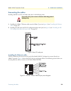
Power LED indicator
The power LED shows the power status of the Model 1001MC (see table 12).
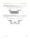
Heartbeat LED indicator
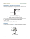
Fault LED indicator
PPP LED indicator
Note The PPP capability will be included in future releases as a software
upgrade to the 1001MC.
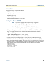
Where to go next
Congratulations, you have finished installing the Model 1001MC! Now go to chapter 3, “Getting started” on
page 36.
Table 11. Ethernet LED indicators
LED Color Function Description
LI Green Twisted pair link indication On = Connected to active LAN
Off = Not connected to active LAN
TD Yellow/Green Transmit data from 1001MC
to LAN
Yellow = Idle condition
Green = Toggles yellow/green with activity
RD Yellow/Green Receive data at 1001MC from LAN Yellow = Idle condition
Green = Toggles yellow/green with activity
Table 12. Power LED indicator
LED Color Function Description
Power Green Power status On = Power is ON
Off = Power is OFF
Table 13. Poll LED indicator
LED Color Function Description
Poll Yellow Heartbeat Toggles when packet TX is on the backplane bus
Table 14. Fault LED indicator
LED Color Function Description
Fault Red Fault condition On = Signals hardware fault
Off = No hardware fault