


Model 2701RC Configuration Slot X page MIB variables description 146
Model 1001MC Operations Guide 7 • Model 2701RC management
CRC4 Error Alarm Threshold (crc4Threshold)
The valid setting for the threshold is 0 to 255. By setting a threshold, the CRC4 Alarm counter will not issue
the error/warning, Syslog, and SNMP Trap message unless the accumulating CRC4 Error Counter is greater
than the threshold. The
Record Current Configuration button will store the setting of the alarm threshold.
Input Mode (mode2701RC)
The following settings are available:
• onLine(0)
• superVisoryMode(1)
To make configuration changes to the NetLink-E1 NTUs, you must first set this bit to superVisoryMode(1).
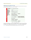
When the Input Mode is set to superVisoryMode1), the Modify Configuration hyperlink will appear. Select
the
Modify Configuration hyperlink. The Model 2701 Configuration page will appear (see section “Model
2701 Configuration page MIB variables description” on page 149 for more information). After making config-
uration changes to the NetLink-E1 NTUs in the Model 2701RC
Configuration page, return to this page by
clicking on the
Back… hyperlink and place the Input Mode variable back to onLine(0). This will notify the
Model 1001MC that the configuration has completed and will cause it to copy the new configuration into the
NetLink-E1 NTU configuration space. If this is not done, the NetLink-E1 NTU will not recognize the config-
uration changes that were made.
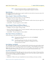
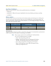
Model 2701 Configuration Slot page Configuration Status table description
The Configuration Status table shows the configuration for the set of units. There are columns for the local and
remote units. If a field is highlighted in yellow, it signifies one of two possible conditions:
• At start up, the Model 1001MC will display a default configuration for the card and all fields will be high-
lighted in yellow, notifying you that the information has not been verified. During the negotiation phase,
the NetLink-E1 NTU modem will update the configuration in the Model 1001MC with its last set of
stored parameters. As these fields are updated in the Model 1001MC, the yellow highlighting will disap-
pear, signifying that the information has been updated. After the local and remote units are linked, the units
will begin updating the remote information in the table, and Line Status set to datamode(2).
• If a rack card is installed in the rack without a customer premise unit connected, the remote information
will be left as either none or highlighted in yellow, notifying you that the information has not been verified.
The following sections define the MIB variables that are shown in the Configuration Status table.
Configuration Status (configStatus2701RC)
This is the title of the status table and displays the configuration status of the rack card. The following status
can be displayed:
• Negotiating(0)—The 1001MC is receiving the rack card’s configuration for the first time
• Static(1)—The 1001MC is showing the updated and correct configuration for the 2701RC
• ImplementingChanges(2)—The 1001MC is updating configuration changes to the 2701RC.
Local Model Code (localModelCode/remoteModelCode)
These variables display the local and remote models codes for the units that were found in the specified address.