


Creating and modifying global configuration templates 162
Model 1001MC Operations Guide 7 • Model 2701RC management
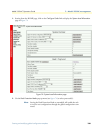
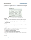
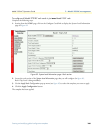
• Tx Clock Timing, this selects the source of the DTE Transmit Clock signal. Note that Clock Mode above
is for the transmitted E1 signal.
- external(0)—Use only when the Clock Mode is set to external-CLK(2).
- internal(1)—Use when the Clock Mode is set to either internal-CLK(1) or networtk-CLK(0).
• FP Switch (Front Panel
- disabled (0)—disables the toggle switches on the front panel of the 2701RC rack card
- enabled(1)—enables the ability to use the front panel toggle switches
• In Band Loops, the two in-band loops are the CSU loop and the V.54 loop.
- disabled(0)—neither loop can be enabled.
- enabled(1)—one of the in-band loops can be enabled depending on the selection of the RDL Type.
• RDL Type
- csu(1)—Selects the in-band loop which is initiated as the standard CSU loopback.
- v54(2)—functions as defined by the V.54 remote Loopback.
• Test Mode DTE, refers to the initiation of loopbacks via one of the DTE signals.
- disabled(0)—no loopbacks can be initiated by a DTE signal
- enabled(1)—Loopbacks can be initiated by a DTE signal.
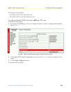
Refer to section “Applying a template” on page 164 to activate the template.