


Installing NetLink modem cards 27
Model 1001MC Operations Guide 2 • Hardware installation
Setting the 2701RC system address
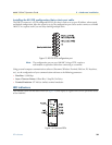
The manual that was shipped with your NetLink-E1 unit specifies switch S3 for the card address in the
NetLink System. Each card in the chassis is given a unique address through the setting of switch S3.
Note Standalone units use the address of the rack card that they are con-
nected to.
Polling overview. The Model 1001MC sends “poll” messages along the internal bus looking for cards installed
in the system. Once a card is found it is placed “online” and communication with the management station
can begin.
If the address of the NetLink modem is not configured or does not match the address range of the rack that it
is installed in, the Model 1001MC may not recognize the card. The address range that is polled is determined
by the configuration of the system. The system administrator must make sure that the software configuration
within the Model 1001MC matches the hardware configuration of the system.
Polling rack #1 and daisy-chained racks. The Model 1001MC uses the number of power supplies in the sys-
tem to determine what the address range of the individual racks will be. The number of power supplies
installed in each rack is entered on the Modem Information page. If the system is set for two power supplies
installed, the 1001MC will automatically set the number of slots available (displayed on the Modem Informa-
tion page) in the chassis to 13. If the system is set for a single power supply installed, the 1001MC will auto-
matically set the number of slots available in the chassis to 15.
Using this information, the Model 1001MC will poll the specified address range in each rack. Thus, in a single
power supply system, the address range for rack #1 (the rack with the 1001MC installed) will be from address
1 to address 15
Note The 1001MC is always address 0.
The 1001MC will then begin polling rack #2 on the daisy chain port starting from address 16. In a redundant
power supply system, the address range for rack #1 (the rack with the 1001MC installed) will be from
address 1 to address 13. The 1001MC will then begin polling rack #2 on the daisy chain port starting from
address 14.
The daisy chained racks are set up in the same manner with 13 addresses being available in a redundant system
and 15 addresses being available in single supply system. When you disable a rack the addresses are still set
aside for that rack space. If a power supply is removed, the addressing will not change unless you make the
change through the 1001MC web pages. This allows easy service of the power supplies.
The 2701RCs are shipped to use DIP switch configuration as default. Software configuration can be enabled
through either the VT-100 screens or through the 1001MC NMS. To use the NMS, switch S2-7 must be set
to the “OFF” position, otherwise the VT-100 port is active.
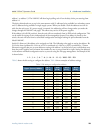
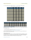
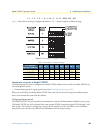
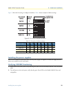
Switch S3 allows a decimal address to be assigned to a link. The following rules apply to setting the address:
• S3-1 is the LSB and S3-8 is the MSB
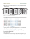
• Patton Electronics suggests that you set your addresses starting with address 1 at the far left of your rack
(farthest away from the power supplies) and increment the numbers by one as you go from left to right. Set-
ting the addresses in this manner will make configuration easier as you start using the web page manage-
ment. An example of this is below.