


Connecting the cables 32
Model 1001MC Operations Guide 2 • Hardware installation
Connecting the cables
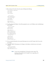
Installing 1001MC rear I/O card cables takes place in the following order:
1. Installing the 10Base-T Ethernet cable onto the 10Base-T port (see figure 9) (see “Installing the Ethernet
cable” on page 32).
2. Installing the cable onto the RS-232 configuration/daisy-chain port (see figure 9) (see “Installing the RS-
232 configuration/daisy-chain port cable” on page 34).
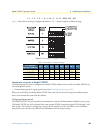
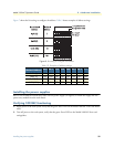
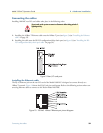
Figure 9. Rear I/O card ports
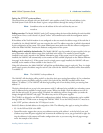
Installing the Ethernet cable
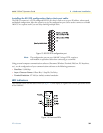
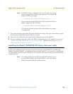
The RJ-45 Ethernet jack on the rear I/O card of the Model 1001MC is designed to connect directly to a
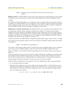
10Base-T network. Figure 10 shows the RJ-45 jack pin-out diagram. Refer to the following sections when con-
structing Ethernet cables to connect to the Patton Model 1001MC.
Figure 10. 1001MC 10Base-T Ethernet port pin-out diagram
Do not work on the system or connect or disconnect cables during periods of
lightning activity.