


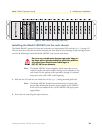
Installing NetLink modem cards 26
Model 1001MC Operations Guide 2 • Hardware installation
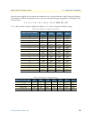
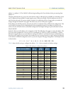
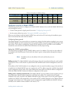
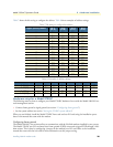
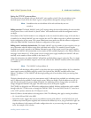
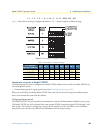
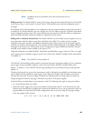
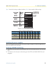
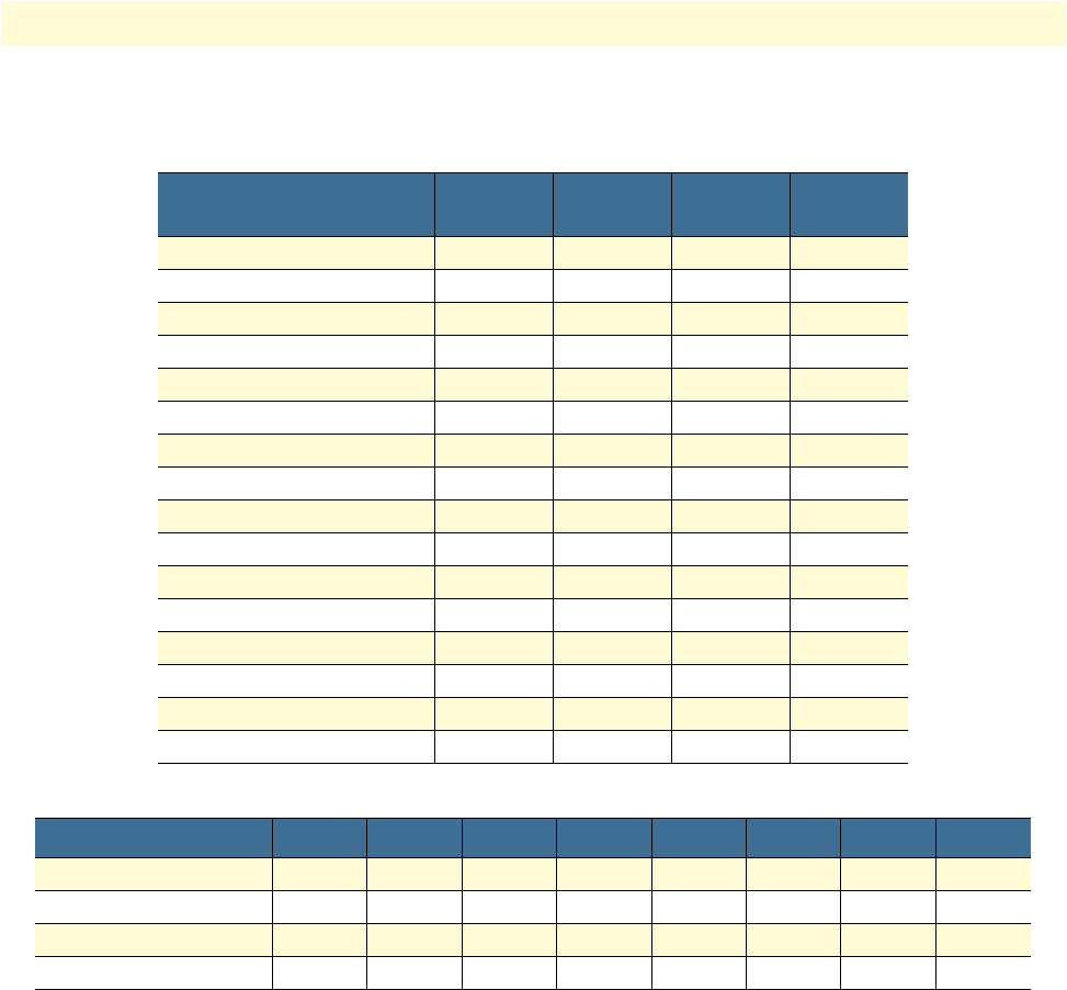
Table 7 shows the bit setting to configure the address. Table 8 shows examples of address settings.
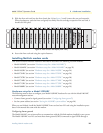
Hardware setup for a Model 2701RC
The following must be done to configure your Model 2701RC hardware for use with the Model 1001MC net-
work management station:
• Connect frame ground to signal ground (see section “Configuring frame ground”)
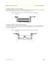
• Set the system address (see section “Setting the 2701RC system address”)
When you are finished, install the Model 2701RC front card and rear I/O card using the installation proce-
dures in the manual that came with the modem.
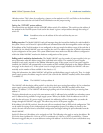
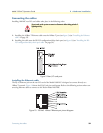
Configuring frame ground
The Model 1001MC uses an internal bus to communicate with the NetLink modems installed in your system.
The Model 2701RC rear I/O card must have frame ground (GND) connected to signal GND through a 100-
ohm resistor. This is done by configuring a jumper on the modem’s rear I/O card. Refer to the installation
manual that came with the rack card for more information on this jumper setting.
Table 7. Bit setting to configure the address
Upper (Lower) Nibble
S1-1
(S1-5)
S1-2
(S1-6)
S1-3
(S1-7)
S1-4
(S1-8)
0 ON ON ON ON
1 ON ON ON OFF
2 ON ON OFF ON
3 ON ON OFF OFF
4 ON OFF ON ON
5 ON OFF ON OFF
6 ON OFF OFF ON
7 ON OFF OFF ON
8 OFF ON ON ON
9 OFF ON ON OFF
A OFF ON OFF ON
B OFF ON OFF OFF
C OFF OFF ON ON
D OFF OFF ON OFF
E OFF OFF OFF ON
F OFF OFF OFF OFF
Table 8. Examples of address settings
Address in Hex (Dec.) S1-1 S1-2 S1-3 S1-4 S1-5 S1-6 S1-7 S1-8
0x01 (1) ON ON ON ON ON ON ON OFF
0x02 (2) ON ON ON ON ON ON OFF ON
0x10(16) ON ON ON OFF ON ON ON ON
0xB5(181) OFF ON OFF OFF ON OFF ON OFF