


Model 1095 Configuration Slot page MIB variables description 106
Model 1001MC Operations Guide 6 • Model 1095RC management
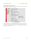
Input Mode (mode1095)
The following settings are available:
• onLine(0)
• superVisoryMode1)
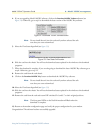
To make configuration changes to the NetLink-mDSL modems, you must first set this bit to
superVisoryMode1). When the Input Mode is set to superVisoryMode1), the
Modify Configuration hyperlink
will appear on the web page next to the
Refresh Current Page hyperlink. Select the Modify Configuration
hyperlink. The
Model 1095RC Configuration—Next Configuration page will appear (see section “Model 1095
Configuration—Next Configuration page MIB variables description” on page 107 for more information).
After making configuration changes to the NetLink-mDSL modems in the Model 1095RC
Update Configura-
tion
page, return to this page and place the Input Mode variable back to onLine(0). This will notify the Model
1001MC that the configuration has completed and will cause it to copy the new configuration into the
NetLink-mDSL configuration space. If this is not done, the NetLink-mDSL will not recognize the configura-
tion changes that were made.
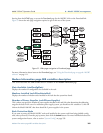
Model 1095 Configuration Slot page Configuration Status table description
The Configuration Status table shows the configuration for the set of units. There are columns for the local and
remote units. If a field is highlighted in yellow, it signifies one of two possible conditions:
• At start up, the Model 1001MC will display a default configuration for the card and all fields will be high-
lighted in yellow, notifying you that the information has not been verified. During the negotiation phase,
the NetLink-mDSL modem will update the configuration in the Model 1001MC with its last set of stored
parameters. As these fields are updated in the Model 1001MC, the yellow highlighting will disappear, signi-
fying that the information has been updated. After the local and remote units are linked, the units will
begin updating the remote information in the table, and Line Status set to datamode(2).
• If a rack card is installed in the rack without a customer premise unit connected, the remote information
will be left as either none or highlighted in yellow, notifying you that the information has not been verified.
The following sections define the MIB variables that are shown in the Configuration Status table.
Model Code (localModelCode/remoteModelCode)
These variables display the local and remote models codes for the units that were found in the specified address.
DTE rate (dteRate1095)
This variable displays the DTE rate for the link. Because the NetLink-mDSL modems are symmetrical (same
rate in both direction), there is only one MIB variable that defines the DTE rate.
Clock Mode (Local-Remote)
This variable defines the clock mode for the NetLink modems. The display shows the Local clock mode (rack
card) and then the remote clock mode.
Tx Data Sample Point (txdEdge1095/remotetxdEdge1095)
This variable defines the sampling point that is used by the NetLink-mDSL modems to read data from the
DTE. In most situations it should always be set to normal(0). In high speed applications, there are situations
that would require an inverted(1) sampling point.