


Installing NetLink modem cards 29
Model 1001MC Operations Guide 2 • Hardware installation
Hardware setup for a Model 2710RC
The following must be done to configure your Model 2710RC hardware for use with the Model 1001MC net-
work management station:
• Connect frame ground to signal ground (see section “Configuring frame ground”)
When you are finished, install the Model 2710RC front card and rear I/O card using the installation proce-
dures in the manual that came with the modem.
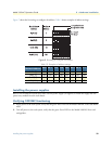
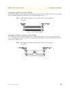
Configuring frame ground
The Model 1001MC uses an internal bus to communicate with the NetLink modems installed in your system.
The Model 2710RC rear I/O card must have frame ground (GND) connected to signal GND through a 100-
ohm resistor. This is done by configuring a jumper on the modem’s rear I/O card. Refer to the installation
manual that came with the rack card for more information on this jumper setting.
Hardware setup for a Model 2715RC
The following must be done to configure your Model 2715RC hardware for use with the Model 1001MC net-
work management station:
• Connect frame ground to signal ground (see section “Configuring frame ground”)
When you are finished, install the Model 2715RC front card and rear I/O card using the installation proce-
dures in the manual that came with the modem.
Configuring frame ground
The Model 1001MC uses an internal bus to communicate with the NetLink modems installed in your system.
The Model 2715RC rear I/O card must have frame ground (GND) connected to signal GND through a 100-
ohm resistor. This is done by configuring a jumper on the modem’s rear I/O card. Refer to the installation
manual that came with the rack card for more information on this jumper setting.
Hardware setup for a Model 3088RC
The following must be done to configure your Model 3088RC hardware for use with the Model 1001MC net-
work management station:
• Connect frame ground to signal ground (see section “Configuring frame ground”)
• Set the system address (see section “Setting the 2701RC system address”)
When you are finished, install the Model 3088RC front card and rear I/O card using the installation proce-
dures in the manual that came with the modem.
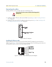
Configuring frame ground
The Model 1001MC uses an internal bus to communicate with the NetLink modems installed in your system.
The Model 3088RC rear I/O card must have frame ground (GND) connected to signal GND through a 100-
ohm resistor. This is done by configuring a jumper on the modem’s rear I/O card. Refer to the installation
manual that came with the rack card for more information on this jumper setting.
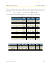
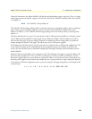
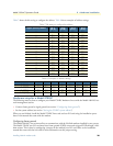
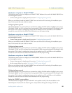
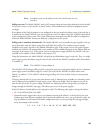
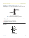
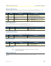
Setting the 3088RC system address
The manual that was shipped with your NetLink-E1 unit specifies switch S3 for the card address in the
NetLink System. Each card in the chassis is given a unique address through the setting of switch S3.