


Slot Configuration 245
Model 1001MC Operations Guide 10 • HTTP/HTML web page reference
To configure the remote circuit ID, type the ID into the Remote Circuit ID text box, then click the Submit but-
ton {located next to the
Remote Circuit ID text box) to save the changes.
Note After submitting the card identification information, you must click
on the
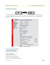
Record Current Configuration button located on the HOME
page to store the configuration changes into memory (see “HOME”
on page 228 for more information).
Clear Remote Circuit ID button. If you want to delete the remote circuit ID information, click on the Clear
Remote Circuit ID
button, then click on the Submit button.
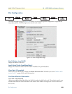
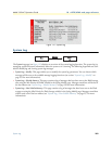
Alarm Information
Clear Slot Alarms (resetStatus)
Selecting this push button erases the alarms (errors and warnings) associated with the specified slot.
Note Errors and warnings will still be listed in the System Log.
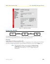
Hardware Reset (resetStatus)
Selecting this button will force the current rack card modem to perform a hardware reset.
Card Lost Indication (cardLostIndication)
This variable lets you choose what type of indication will be made if a modem is removed from the manage-
ment system. The following options are available:
• none(0)
• warning(1)—If a card lost situation occurs, it will be displayed in yellow highlighting as a warning on the
HOME, System Level Information, and Modem Information Rack pages.
• error(2)—If a card lost situation occurs, it will be displayed in red highlighting as an error on the HOME,
System Level Information, and Modem Information Rack pages
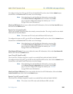
Line Down Indication (lineDownIndication)
This variable allows you to choose what type of indication will be made if a modem reports a line down sce-
nario. The following options are available:
• none(0)
• warning(1)—If a line down situation occurs, it will be displayed in yellow highlighting as a warning on the
HOME, System Level Information, and Modem Information Rack pages.
• error(2)—If a line down situation occurs, it will be displayed in red highlighting as an error on the HOME,
System Level Information, and Modem Information Rack pages
Note Line Down Indication must be set to error(2) in order for line-up and
line-down SNMP trap messages to be sent.