


Introduction 277
Model 1001MC Operations Guide 11 • Troubleshooting and maintenance
Introduction
This chapter describes troubleshooting and fault analysis that can be performed by the operator. This section
contains the following sections to help you troubleshoot the 1001MC rack card and NetLink rack cards:
• Troubleshooting the 100MC rack card (see page 277)
• Troubleshooting network malfunctions (see page 278)
• Running test mode diagnostics (see page 282)
• Replacing a 1001MC rack card (see page 284)
If you require more help, refer to chapter 12, “Contacting Patton for assistance” on page 286.
Troubleshooting the 1001MC rack card
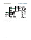
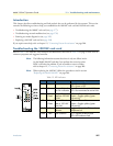
Refer to table 15 for 1001MC LED locations and definitions, then refer to table 16 on page 278 for a list of
common symptoms and suggested remedies.
Note The following information assumes that there is only one failure involv-
ing the Model 1001MC and that if you perform the corrective action
listed, it will solve the problem. If you are unable to correct a failure,
refer to chapter 12, “Contacting Patton for assistance” on page 286.
Note When replacing the 1001MC, follow the procedures cited in section
“Replacing the Model 1001MC” on page 284.
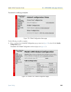
Table 15. LED indicators
LED Color Function Description
Power Green Power status On = Power is ON
Off = Power is OFF
LI Green Ethernet: Twisted-
pair link indication
On = Connected to active LAN
Off = Not connected to active LAN
TD Yellow/
Green
Ethernet: Transmit
data from 1001MC
to LAN
Yellow = Idle condition
Green = Toggles yellow/green
with activity
RD Yellow/
Green
Ethernet: Receive
data at 1001MC
from LAN
Yellow = Idle condition
Green = Toggles yellow/green
with activity
Poll Yellow Heartbeat
indicator
Toggles when packet TX is on the
backplane bus
Fault Red Fault condition On = Signals hardware fault
Off = No hardware fault