


Installing NetLink modem cards 22
Model 1001MC Operations Guide 2 • Hardware installation
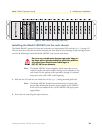
Hardware setup for a Model 1094ARC
The following must be done to configure your Model 1094ARC hardware for use with the Model 1001MC
network management station:
• Connect frame ground to signal ground (see section “Configuring frame ground”)
• Set the system address (see section “Setting the 1094ARC system address”)
When you are finished, install the Model 1094ARC front card and rear I/O card using the installation proce-
dures in the manual that came with the modem.
Configuring frame ground
The Model 1001MC uses an internal bus to communicate with the NetLink modems installed in your system.
The Model 1094ARC rear I/O card must have frame ground (GND) connected to signal GND through a
100-ohm resistor. This is done by configuring a jumper on the modem’s rear I/O card. Refer to the installation
manual that came with the rack card for more information on this jumper setting.
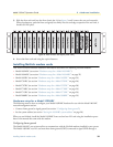
Setting the 1094ARC system address
The manual that was shipped with the 1094RC defines switch S1 as Address. This switch sets the address of
the modem in the NetLink system. Each card in the chassis is given a unique address through the setting of
switch S1.
Note Standalone units use the address of the rack card that they are con-
nected to.
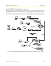
Polling overview. The Model 1001MC sends poll messages along the internal bus looking for cards installed
in the system. Once a card is found it is placed online and communication with the management station
can begin.
If the address of the NetLink modem is not configured or does not match the address range of the rack that it
is installed in, the Model 1001MC may not recognize the card. The address range that is polled is determined
by the configuration of the system. The system administrator must make sure that the software configuration
within the Model 1001MC matches the hardware configuration of the system.
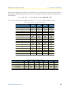
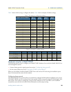
Polling rack #1 and daisy-chained racks. The Model 1001MC uses the number of power supplies in the sys-
tem to determine what the address range of the individual racks will be. The number of power supplies
installed in each rack is entered on the Modem Information page. If the system is set for two power supplies
installed, the 1001MC will automatically set the number of slots available (displayed on the Modem Informa-
tion page) in the chassis to 13. If the system is set for a single power supply installed, the 1001MC will auto-
matically set the number of slots available in the chassis to 15.
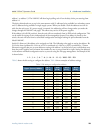
Using this information, the Model 1001MC will poll the specified address range in each rack. Thus, in a single
power supply system, the address range for rack #1 (the rack with the 1001MC installed) will be from address
1 to address 15
Note The 1001MC is always address 0.
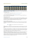
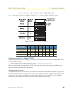
The 1001MC will then begin polling rack #2 on the daisy chain port starting from address 16. In a redundant
power supply system, the address range for rack #1 (the rack with the 1001MC installed) will be from