


Model 2707RC Configuration—Configuration page MIB variables description 184
Model 1001MC Operations Guide 8 • Model 2707RC management
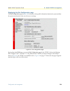
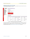
Unit Configuration table
This table shows the configurable MIB variables for the 2707RC card. After changes are made, select the Sub-
mit Query button at the bottom of the table and then place the Input Mode back to onLine(0) in the Model
2707RC Configuration page.
The following sections explain the MIB variables that are shown in the Unit Configuration table.
Line Format (lineFormat)
This option should be set to G.703 unframed: frame-G703(0).
Clock Mode (clockMode2707RC)
This variable defines the clock mode for the NetLink-E1 modems. The following options are available:
• network-CLK(0)
• internal-CLK(1)
• external-CLK(2).
DTE Rate (dteRate2707RC)
This read-only variable displays the DTE rate for the link. This is the Nx64 kbps data rate selected by the
number of activated channels.
Line Coding (lineCoding2707RC)
This variable is used to select the G.703 line coding. The following options are available:
• code-HDB3(0)—HDB3
• code-AMI(1)—AMI
Line Build Out (lineBuildOut)
This is used to select the line build out. The following options are available:
• lbo-75ohm(0)—75 ohm
• lbo-120ohm(1)—120 ohm
FP Switches (frntSwitch)
This selects if the front panel toggle switches used for loopbacks and pattern generators are enabled(1) or dis-
abled(0).
H/W Test mode (testModeSetInd)
This read-only variable displays any test mode invoked from the toggle switches and DTE test mode lines. If
the unit is in a test mode, this option will be highlighted in blue.
S/W Test mode (testModeSet2707RC)
This is used to invoke test modes through the NMS. The only valid options for the 2707RC are:
• off(0)
• lal(4)—Local loopback