


Section 11 Multi-Function Timer Pulse Unit 2
Page 606 of 2108 R01UH0134EJ0400 Rev. 4.00
Sep 24, 2014
SH7262 Group, SH7264 Group
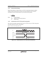
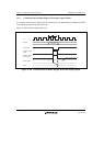
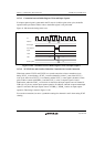
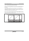
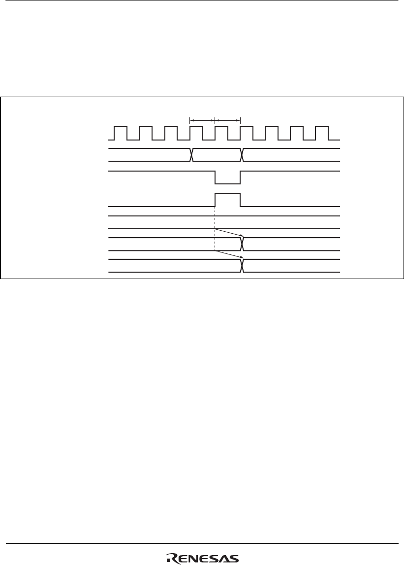
11.7.11 Contention between Buffer Register Write and Input Capture
If an input capture signal is generated in the T2 state of a buffer register write cycle, the buffer
operation takes precedence and the write to the buffer register is not performed.
Figure 11.106 shows the timing in this case.
Input capture
signal
Write signal
Address
TCNT
Buffer register write cycle
T1
T2
N
TGR
N
M
M
Buffer register
Buffer register
address
Pφ
Figure 11.106 Contention between Buffer Register Write and Input Capture
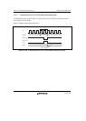
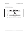
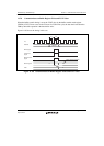
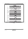
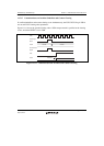
11.7.12 TCNT2 Write and Overflow/Underflow Contention in Cascade Connection
With timer counters TCNT1 and TCNT2 in a cascade connection, when a contention occurs
during TCNT_1 count (during a TCNT_2 overflow/underflow) in the T
2
state of the TCNT_2
write cycle, the write to TCNT_2 is conducted, and the TCNT_1 count signal is disabled. At this
point, if there is match with TGRA_1 and the TCNT_1 value, a compare signal is issued.
Furthermore, when the TCNT_1 count clock is selected as the input capture source of channel 0,
TGRA_0 to D_0 carry out the input capture operation. In addition, when the compare match/input
capture is selected as the input capture source of TGRB_1, TGRB_1 carries out input capture
operation. The timing is shown in figure 11.107.
For cascade connections, be sure to synchronize settings for channels 1 and 2 when setting TCNT
clearing.