


Page 2070 of 2108 R01UH0134EJ0400 Rev. 4.00
Sep 24, 2014
Item Page Revision (See Manual for Details)
11.3.23 Timer Cycle Data
Register (TCDR)
498 Description amended
TCDR is a 16-bit register used only in complementary
PWM mode. Set half the PWM carrier sync value (a value
of two times TDDR + 3 or greater) as the TCDR register
value. This register is constantly compared with the TCNTS
counter in complementary PWM mode, and when a match
occurs, the TCNTS counter switches direction (decrement
to increment).
11.4.2 Synchronous
Operation
513 Description amended
Channels 0 to 4 can all be designated for synchronous
operation.
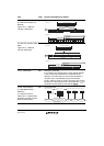
11.4.4 Cascaded Operation
Table 11.42 Cascaded
Combinations
519 Description amended
For simultaneous input capture of TCNT_1 and TCNT_2
during cascaded operation, additional input capture input
pins can be specified by the input capture control register
(TICCR). The edge detection that is the condition for input
capture uses a signal representing the logical OR of the
original input pin and the added input pins. For details, see
(4) Cascaded Operation Example (c).
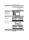
(1) Example of Cascaded
Operation Setting Procedure
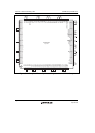
Figure 11.20 Cascaded
Operation Setting Procedure
520 Figure amended
[1] Set bits TPSC2 to TPSC0 in the channel 1
TCR to B'111 to select TCNT_2 overflow/
underflow counting.
(4) Cascaded Operation
Example (c)
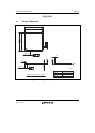
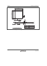
Figure 11.23 Cascaded
Operation Example (c)
522 Figure replaced
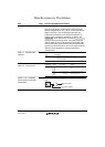
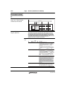
11.4.5 PWM Modes
PWM mode 2
524 Description amended
PWM output is generated using one TGR as the cycle
register and the others as duty registers. The output
specified in TIOR is performed by means of compare
matches. Upon counter clearing by a cycle register
compare match, the output value of each pin is the initial
value set in TIOR.