


Section 38 States and Handling of Pins
R01UH0134EJ0400 Rev. 4.00 Page 2059 of 2108
Sep 24, 2014
SH7262 Group, SH7264 Group
38.3 Handling of Pins in Deep Standby Mode
How pins are to be handled in deep standby mode is indicated below.
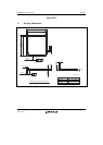
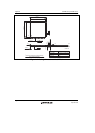
For the states of pins in deep standby mode, refer to the corresponding items under section, 38.1,
Pin States. Handling of unused pins as described under section 38.2, Treatment of Unused Pins,
also applies in deep standby mode.
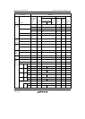
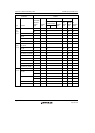
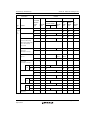
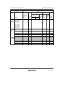
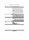
Table 38.5 Handling of Pins in Deep Standby Mode
Pin Handling
1.2-V power (Vcc, PLLVcc,
USBDVcc, USBUVcc, USBAVcc)
Supply power at 1.2 V
3.3-V power (PVcc, AVcc,
USBDPVcc, USBAPVcc)
Supply power at 3.3 V
Ground (Vss, PLLVss, USBDVss,
USBUVss, USBAVss, AVss,
USBDPVss, USBAPVss)
Connect to ground
VBUS Fix the level on this pin (pull it up or down, or connect it to
the power-supply or ground level) or open circuit. However,
note that current as indicated in table 37.2, DC
Characteristics (2) [Current Consumption] will be drawn by
the pin fixed to the high level.
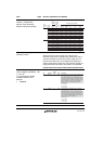
REFRIN Connect this pin to USBAPVss via a 5.6 k 1 % resistor
AVref Fix the level on this pin (from 3.0 V to AVcc)
EXTAL, RTC_X1, USB_X1 Connect the pins to the crystal oscillator or the clock-input
signal, or to a fixed level (pull them up or down, or connect
them to the power-supply or ground level)
XTAL, RTC_X2, USB_X2 Connect the pins to the crystal oscillator or open circuit
Dedicated input pins other than
those listed above
Fix the level on the pins (pull them up or down, or connect
them to the power-supply or ground level).
Input/output pins (other than those
listed above) in the input state
Fix the level on the pins (pull them up or down).
Input/output pins (other than those
listed above) in the high-impedance
state
Fix the level on the pins (pull them up or down) or open
circuit.