


Section 33 Power-Down Modes
R01UH0134EJ0400 Rev. 4.00 Page 1815 of 2108
Sep 24, 2014
SH7262 Group, SH7264 Group
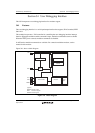
(3) Operation after Canceling Deep Standby Mode
After canceling deep standby mode, the LSI can be activated through the external memory or from
the on-chip data-retention RAM, which can be selected by setting the RAMBOOT bit in DSCTR.
By setting the EBUSKEEPE bit, the states of the external memory control pins can be retained
even after cancellation of deep standby mode. Table 33.3 shows the pin states after cancellation of
deep standby mode according to the setting of each bit. Table 33.4 lists the external memory
control pins.
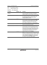
Table 33.3 Pin States after Cancellation of Deep Standby Mode and System Activation
Method by the DSCTR Settings
EBUSKEEPE
Bit
RAMBOOT
Bit
Activation
Method
Pin States After Cancellation of Deep Standby
Mode
0 0 External
memory
The states of the external memory control pins are not
retained.
For other pins, the retention of their states is cancelled when
the IOKEEP bit is cleared.
0 1 On-chip data-
retention RAM
The states of the external memory control pins are not
retained.
After cancellation of deep standby mode, the retention of the
external memory control pin states is cancelled.
For other pins, the retention of their states is cancelled when
the IOKEEP bit is cleared.
1 0 Setting prohibited.
1 1 On-chip data-
retention RAM
The states of the external memory control pin are retained.
The retention of the states of the external memory control
pins and other pins is cancelled when the IOKEEP bit is
cleared.
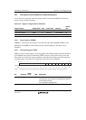
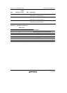
Table 33.4 External Memory Control Pins in Different Modes
Boot Mode 0
(CS0 Area)
Boot Mode 2
(NAND Flash Memory)
Boot Mode 1, 3
(Serial Flash Memory)
A[20:1]
D[15:0]
CS0, RD, CKIO
NAF[7:0]
FRE, FCLE, FALE, FEW, FCE,
FRB
RSPCK0, SSL00, MOSI0,
MISO0