


Section 9 Bus State Controller
Page 236 of 2108 R01UH0134EJ0400 Rev. 4.00
Sep 24, 2014
SH7262 Group, SH7264 Group
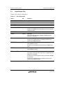
Table 9.3 Initial States of Areas in Boot Modes 0, 2, and 3
Boot Mode Item Area 0 Areas 1 to 6
0 Data bus width Fixed to 16 bits. Not changeable. The initial state is 16 bits.
Can be changed by program.
Endian
specification
Fixed to big endian.
Not changeable.
The initial state is big endian.
Can be changed by program.
Settings of pins
related to this
module
Pin functions for A20 to A1, D15 to D0, CS0, and RD are set
automatically. Other pins need to be set by program.
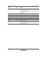
1 to 3 Data bus width The initial state is 16 bits. Can be changed by program.
Endian
specification
The initial state is big endian. Can be changed by program.
Settings of pins
related to this
module
General I/O function.
For external bus access, all the necessary pins need to be set by
program.
Notes: 1. In order to connect boot ROM using address lines A21 and above in boot mode 0, pull-
down processing must be provided on the board for address lines A21 and above.
2. Depending on the type of memory used, there may be limitations on the data bus width.
For details, see 9.4.2, CSn Space Bus Control Register.
3. Since the CS1 and A0 functions are assigned to the same pin, it is not possible to use
area 1 and a device with an 8-bit bus connection at the same time.
4. Since the CS4 and A22 functions are assigned to the same pin, it is not possible to use
area 4 and a device using address lines A22 and above at the same time.