


Section 20 Controller Area Network
R01UH0134EJ0400 Rev. 4.00 Page 981 of 2108
Sep 24, 2014
SH7262 Group, SH7264 Group
Section 20 Controller Area Network
20.1 Summary
20.1.1 Overview
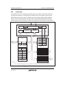
This document primarily describes the programming interface for the controller area network
(Renesas CAN Time Trigger Level 1) module. It serves to facilitate the hardware/software
interface so that engineers involved in this module implementation can ensure the design is
successful.
Deep standby mode can be canceled by change on CRxn (PJ3, PJ1) pin. For details, refer to
section 33, Power-Down Modes.
20.1.2 Scope
The CAN Data Link Controller function is not described in this document. It is the responsibility
of the reader to investigate the CAN Specification Document (see references). The interfaces from
the CAN Controller are described, in so far as they pertain to the connection with the User
Interface.
The programming model is described in some detail. It is not the intention of this document to
describe the implementation of the programming interface, but to simply present the interface to
the underlying CAN functionality.
The document places no constraints upon the implementation of this module in terms of process,
packaging or power supply criteria. These issues are resolved where appropriate in
implementation specifications.
20.1.3 Audience
In particular this document provides the design reference for software authors who are responsible
for creating a CAN application using this module.
In the creation of this module user interface LSI engineers must use this document to understand
the hardware requirements.
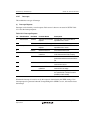
20.1.4 References
1. CAN Specification Version 2.0 part A, Robert Bosch GmbH, 1991
2. CAN Specification Version 2.0 part B, Robert Bosch GmbH, 1991