


Section 11 Multi-Function Timer Pulse Unit 2
R01UH0134EJ0400 Rev. 4.00 Page 441 of 2108
Sep 24, 2014
SH7262 Group, SH7264 Group
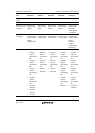
11.3.1 Timer Control Register (TCR)
The TCR registers are 8-bit readable/writable registers that control the TCNT operation for each
channel. This module has a total of five TCR registers, one each for channels 0 to 4. TCR register
settings should be conducted only when TCNT operation is stopped.
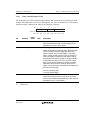
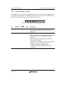
Bit:
Initial value:
R/W:
7654321
0
00000000
R/W R/W R/W R/W R/W R/W R/W R/W
CCLR[2:0] CKEG[1:0] TPSC[2:0]
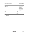
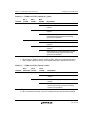
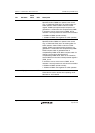
Bit Bit Name
Initial
Value R/W Description
7 to 5 CCLR[2:0] 000 R/W Counter Clear 0 to 2
These bits select the TCNT counter clearing source.
See tables 11.4 and 11.5 for details.
4, 3 CKEG[1:0] 00 R/W Clock Edge 0 and 1
These bits select the input clock edge. When the input
clock is counted using both edges, the input clock
period is halved (e.g. P/4 both edges = P/2 rising
edge). If phase counting mode is used on channels 1
and 2, this setting is ignored and the phase counting
mode setting has priority. Internal clock edge selection
is valid when the input clock is P/4 or slower. When
P/1, or the overflow/underflow of another channel is
selected for the input clock, although values can be
written, counter operation compiles with the initial value.
00: Count at rising edge
01: Count at falling edge
1x: Count at both edges
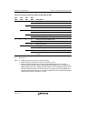
2 to 0 TPSC[2:0] 000 R/W Time Prescaler 0 to 2
These bits select the TCNT counter clock. The clock
source can be selected independently for each channel.
See tables 11.6 to 11.9 for details.
[Legend]
x: Don't care